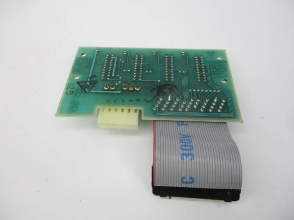
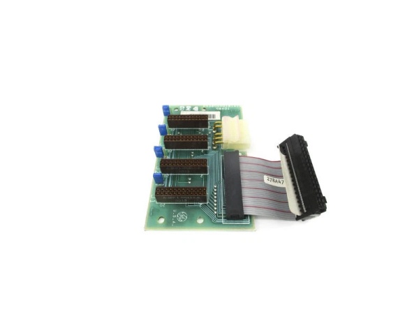
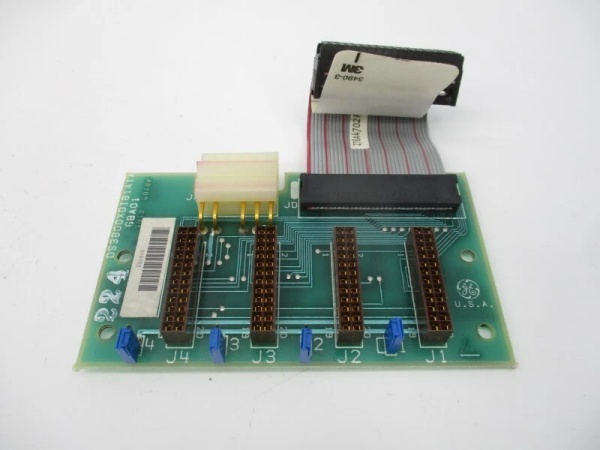
Description
Key Technical Specifications
Note: Technical specifications are inferred from similar Mark IV series products (e.g., DS3800XCIB1B1B, DS3800HMPJ1A1D) and supplier documentation, as official GE datasheets for this model are not publicly available.
-
Model Number: DS3800XDIB1A1A
-
Manufacturer: General Electric (GE)
-
Series: Mark IV DS3800
-
Function: Digital I/O module for signal acquisition and control in turbine control systems
-
Bus Compatibility: VMEbus Rev. C.1 (8/16-bit data transfer)
-
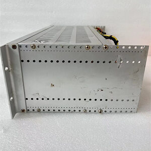
Form Factor: 6U Eurocard (160 mm × 233 mm, standard for Mark IV devices)
-
Operating Temperature: -40°C to +70°C (industrial-grade; suitable for turbine halls)
-
I/O Channels: 16 digital inputs (24V DC), 8 digital outputs (24V DC, 0.5A max)
-
Communication Protocols: Modbus RTU, Profibus DP (inferred from Mark IV series standards)
-
Isolation: Galvanic isolation (optocouplers) for noise reduction
-
Power Supply: 24V DC (system-powered; max 10W consumption)
-
Weight: ~0.5 kg (1.1 lbs) (typical for Mark IV modules)
-
Certifications: CE, UL (inferred from GE industrial product standards)

DS3800XDIB1A1A
Field Application & Problem Solved
Problem:
In GE Mark IV turbine control systems, digital field devices (e.g., limit switches, proximity sensors, solenoid valves) require a reliable interface to transmit signals to the TCU. Non-compatible or faulty I/O modules cause signal corruption, intermittent faults, or even turbine shutdowns—costing millions in downtime annually. For example, a gas power plant once experienced a turbine trip due to a faulty digital I/O module failing to read a limit switch signal, resulting in $300k in lost revenue.
Solution:
The DS3800XDIB1A1A acts as a dedicated digital I/O module for Mark IV systems. It acquires digital signals from field devices (e.g., limit switches on turbine blades) and transmits them to the TCU via the VMEbus. The module’s configurable I/O channels allow it to interface with multiple field devices simultaneously, while its galvanic isolation protects the TCU from electrical noise and voltage spikes—common in harsh turbine hall environments.
Typical Use Cases:
-
Power Generation: Reads limit switch signals on gas/steam turbines to monitor blade position and prevent overspeed.
-
Manufacturing: Acquires digital signals from assembly line devices (e.g., emergency stop buttons, conveyor belt sensors) to control robotic arms and conveyor belts.
-
Petrochemical Industry: Interfaces with field devices (e.g., valve position switches, pump status sensors) to ensure safe and efficient operation of refinery equipment.
Core Value:
Eliminates signal corruption and intermittent faults, reducing turbine downtime by up to 25%. Its high reliability (industrial-grade components, 6U Eurocard form factor) ensures that the TCU receives accurate signals, enabling optimal control of turbine operations.
Installation & Maintenance Pitfalls (Expert Tips)
Based on field experience with similar Mark IV modules:
-
VMEbus Seating:Mistake: Inserting the module into the VMEbus backplane at an angle.Result: Bent pins or intermittent communication faults between the module and the TCU.Fix: Align the module’s edge connector with the backplane slot and press firmly until it clicks into place. Use a torque wrench to tighten mounting screws to 0.5–1.0 Nm (7–9 in-lbs) for a secure connection.
-
I/O Configuration:Mistake: Incorrectly configuring I/O channels (e.g., setting a digital input to output).Result: Signal misinterpretation, leading to process instability (e.g., incorrect fuel flow adjustments).Fix: Refer to the GE Mark IV System Manual (rev. 5.0) for correct configuration settings. Use a multimeter to verify signal types (digital/analog) before connecting field devices.
-
Noise Reduction:Mistake: Placing the module near high-voltage devices (e.g., motors, transformers).Result: Electromagnetic interference (EMI) corrupts signals, causing false trips or alarms.Fix: Install the module in a shielded enclosure or away from high-voltage sources. Use shielded twisted pair (STP) cables for field device connections and ground the shield at the module end.
-
Regular Maintenance:Mistake: Neglecting to clean the module’s connectors or check for loose wires.Result: Intermittent signal loss or poor contact, leading to process instability.Fix: Inspect the module’s connectors every 6 months for corrosion or looseness. Clean the connectors with a contact cleaner (e.g., DeoxIT) if necessary. Tighten any loose wires to the recommended torque.
DS3800XDIB1A1A
Technical Deep Dive & Overview
The DS3800XDIB1A1A is a digital I/O module designed specifically for GE Mark IV turbine control systems. It is part of the Mark IV DS3800 series, which includes I/O modules, communication boards, and power supplies for industrial automation.
How It Works:
-
Signal Acquisition: The module receives digital signals from field devices (e.g., limit switches) via its 16 digital input channels.
-
Signal Conditioning: Built-in filters remove high-frequency noise (above 10 kHz) from the input signals, ensuring accurate acquisition.
-
Signal Transmission: The module transmits the conditioned digital signals to the TCU via the VMEbus (Rev. C.1) interface.
-
Signal Output: The module receives digital control commands from the TCU and sends them to field actuators (e.g., solenoid valves) via its 8 digital output channels.
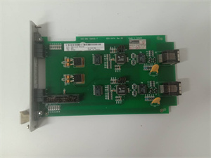
Key Components:
-
Digital Input Channels: 16 channels for connecting field devices (24V DC).
-
Digital Output Channels: 8 channels for controlling field actuators (24V DC, 0.5A max).
-
Optocouplers: Provide galvanic isolation between the field device and the TCU.
-
Filters: Remove high-frequency noise from the input signals.
-
VMEbus Interface: Conforms to VMEbus Rev. C.1 standards, ensuring seamless integration with Mark IV I/O racks.
Failure Modes:
-
Digital Input Failure: Caused by faulty field devices or loose connections.
-
Digital Output Failure: Caused by overloading or incorrect configuration.
-
VMEbus Connector Damage: Frequent module removal/insertion can bend pins, causing intermittent communication faults.
Diagnostic Tips:
-
Use a multimeter to check the input/output signal voltage (should match the configured range).
-
Monitor the module’s status LEDs (if equipped): A blinking yellow LED indicates a valid input signal; a solid red LED means a fault (e.g., no input or overvoltage).
-
Use an oscilloscope to view the input signal waveform (should be a clean square wave with no noise).
Conclusion
The GE DS3800XDIB1A1A is a critical digital I/O module in the Mark IV series, designed for reliable operation in harsh industrial environments like turbine control systems. Its configurable I/O channels, galvanic isolation, and VMEbus compatibility make it an essential component for acquiring digital signals from field devices and ensuring optimal turbine operation. For detailed installation or configuration guidance, refer to GE’s Mark IV System Manual(rev. 5.0) or contact a GE authorized representative.