Description
System Architecture & Operational Principle
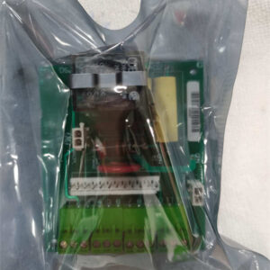
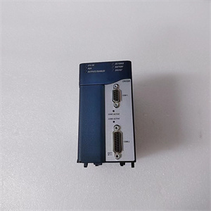
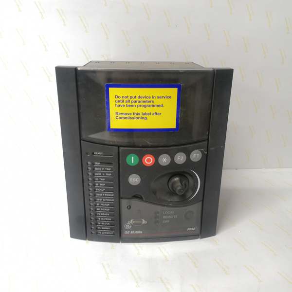
The GE F650CFBF1G0HI10HBNA is a rack-mounted digital feeder protection relay (1/2 rack width, panel mount) designed for deployment in substation control cabinets (Purdue Model Level 2). It acts as the “brain” of the feeder protection system, receiving analog signals (current/voltage from CTs/VTs) and digital signals (status from circuit breakers, switches) from the field. These signals are processed by an internal microprocessor, which executes protection algorithms (e.g., overcurrent, earth fault) and generates control commands (e.g., trip signals to circuit breakers).
Upstream, it connects to SCADA systems or substation automation systems via Ethernet (10/100 Base TX) or serial (RS485) links for remote monitoring and configuration. Downstream, it outputs trip/close commands to circuit breakers and status signals to local HMIs or remote operators. The modular design (draw-out construction) allows for quick replacement, reducing downtime during maintenance.
A key advantage is its compliance with IEC 61850 (certified), which enables seamless integration with modern substation communication networks. The 40-character backlit LCD provides local access to real-time values (current, voltage) and fault reports, reducing reliance on external devices for basic operations.
Core Technical Specifications
-
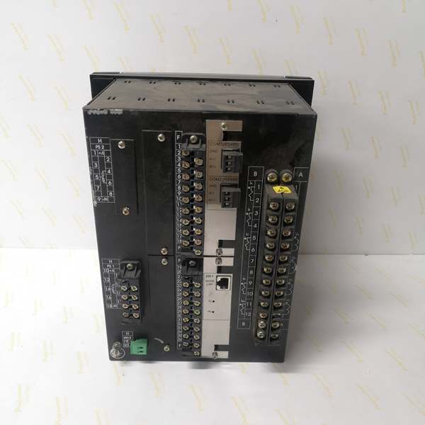
Physical Interface: 1/2 rack width (96mm), panel mount
-
Signal Type: Analog (current/voltage) + Digital (status/control)
-
Channel Density: 16 digital inputs, 12 relay outputs, 4-20mA analog inputs
-
Communication Bus: Ethernet (10/100 Base TX), RS485 (Modbus/DNP3.0)
-
Environmental Tolerance: Operating temperature: -40°C to +70°C; storage: -40°C to +85°C
-
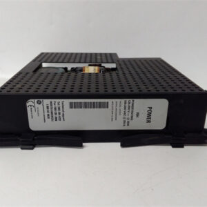
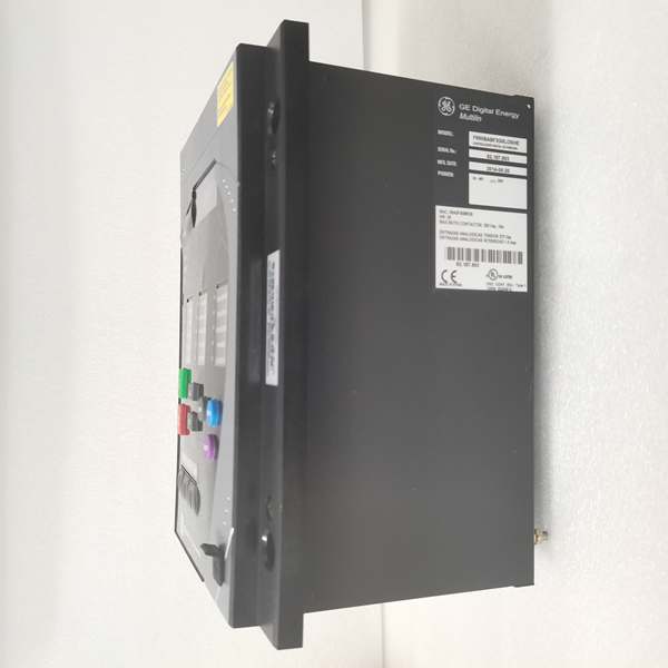
Power Draw: 30W (max) @ 48-250V DC / 110-240V AC
-
Protection Functions: Overcurrent, earth fault, directional, distance, breaker failure
-
Measurement Accuracy: ±0.5% (voltage/current), ±0.1 Hz (frequency)
-
Certifications: IEC 61850, IEEE C37.90, ANSI/IEEE standards
Customer Value & Operational Benefits
Reduced Downtime with Advanced Protection
The F650CFBF1G0HI10HBNA’s high-speed overcurrent protection (trip time <10 ms) and arc flash detection minimize equipment damage during faults. For example, in a distribution substation, it can quickly isolate a faulted feeder, preventing cascading outages and reducing downtime by up to 30%.
Simplified Integration with Existing Systems
With support for IEC 61850, Modbus, and DNP3.0, the relay integrates seamlessly with legacy SCADA systems. A utility company in the Midwest reported a 25% reduction in integration time when upgrading from an older electromechanical relay to the F650 series.
Lower Maintenance Costs via Modular Design
The draw-out construction allows technicians to replace the relay without disturbing field wiring, cutting maintenance time by 50%. Additionally, the event log (stores up to 1000 events) and waveform capture simplify troubleshooting, reducing the need for expensive diagnostic tools.
Field Engineer’s Notes (From the Trenches)
When installing the F650CFBF1G0HI10HBNA, always verify the auxiliary voltage before powering up. I once worked on a project where the site supplied 250V AC instead of the required 120V AC—luckily, the relay’s wide voltage range (110–240V AC) prevented damage, but it caused unexpected behavior until we corrected the supply.Another gotcha: grounding the shield of the RS485 cable is critical. I’ve seen intermittent communication faults traced to ungrounded shields, which pick up electromagnetic interference from nearby power lines. Use a shielded twisted-pair cable with the shield connected to the relay’s ground terminal.For troubleshooting, start with the LED indicators on the front panel: a steady green light means power is good, while a flashing red light indicates a fault (e.g., communication loss). The event log (accessible via the serial port) will tell you exactly what happened—don’t skip this step!
Real-World Applications
-
Distribution Substation Feeder ProtectionThe F650CFBF1G0HI10HBNA monitors current and voltage on a 13.8 kV feeder, detecting overcurrent and earth faults. When a fault occurs, it sends a trip signal to the circuit breaker, isolating the faulted section. The breaker failure protection (50BF) ensures that if the breaker fails to trip, a backup trip signal is sent to adjacent breakers.
-
Industrial Motor Control Center (MCC)In a manufacturing plant, the relay protects a 480V motor feeder from overcurrent and locked rotor conditions. The thermal image function (49) tracks motor temperature, preventing overheating and extending motor life. The Modbus TCP interface allows the plant’s SCADA system to monitor motor status remotely.
High-Frequency Troubleshooting FAQ
Q: What do the LED indicators on the F650CFBF1G0HI10HBNA mean?
A: The front panel has two LEDs: green (power/communication) and red (fault). A steady green light indicates the relay is powered and communicating with the SCADA system. A flashing red light means a fault (e.g., overcurrent, communication loss)—check the event log via the serial port for details.
Q: Can the F650CFBF1G0HI10HBNA be replaced with a newer model like the F650BABF1G0HI?
A: Yes, but verify compatibility with the existing system. The F650BABF1G0HI has a larger graphic display (instead of basic) and supports IEC 61850 Edition 2, but the I/O configuration (16DI/12DO) is the same. Ensure the new relay’s communication protocols (e.g., Modbus TCP) match the SCADA system.
Q: How do I troubleshoot a communication fault with the SCADA system?
A: First, check the Ethernet cable (use a cable tester to verify continuity). Next, confirm the IP address (via the serial port) matches the SCADA system’s configuration. If using RS485, check the baud rate (9600 bps default) and termination resistors (120 ohms at each end of the bus).
Q: What is the maximum distance for the RS485 communication?
A: The F650CFBF1G0HI10HBNA supports RS485 up to 1200 meters (4000 feet) with a shielded twisted-pair cable. For longer distances, use a fiber optic converter (available as an option).
Commercial Availability & Pricing
Please note: The listed price is not the actual final price. It is for reference only and is subject to appropriate negotiation based on current market conditions, quantity, and availability.