Description
System Architecture & Operational Principle
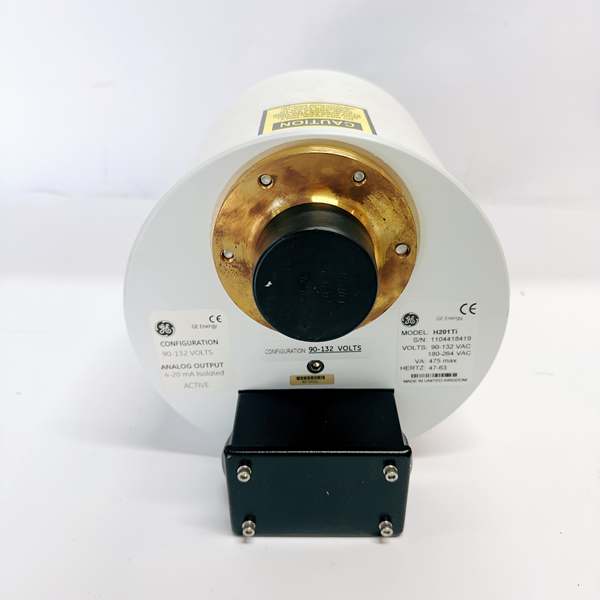
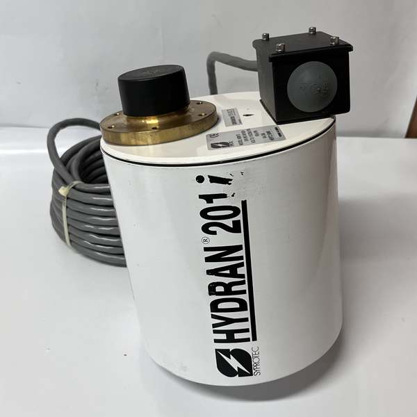
The GE H201TI is a compact, microprocessor-based transmitter mounted on a transformer’s oil sampling valve. It extracts dissolved gases through a vacuum-resistant membrane and analyzes them with a HYDRAN® fuel cell sensor. In the automation topology, it sits at the device level (Purdue Model Level 0/1), interfacing directly with the physical asset. Upstream, it receives power and communicates via RS-485 from the H201Ci-1 controller. Downstream, it outputs gas concentration data (digital via RS-485, optional analog 4-20mA) and triggers alarms based on configurable thresholds. Its key advantage is the galvanic isolation between the sensor circuit and communication ports, which prevents ground loops common in substation environments. The modular design allows for hot-swap replacement of the sensor head without rewiring the main enclosure.
Core Technical Specifications
-
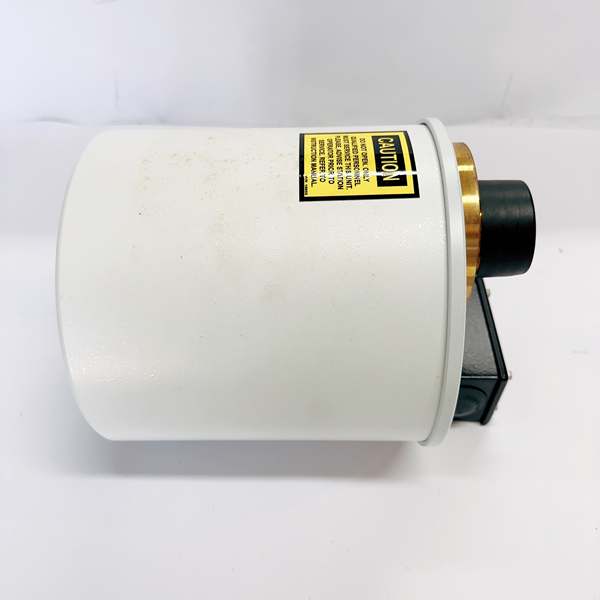
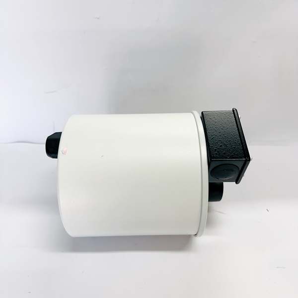
Physical Interface: Brass adapter for oil valve, IP66-rated enclosure
-
Signal Type: Analog (4-20mA isolated, optional) + Digital (RS-485)
-
Gas Coverage: Hydrogen (H₂), CO, C₂H₂, C₂H₄
-
Measurement Range: 0–2000 ppm (H₂ equivalent)
-
Accuracy: ±10% of reading ±25 ppm (H₂)
-
Response Time: <10 minutes (90% step change)
-
Communication Bus: RS-485 (Modbus RTU/Hydran protocol), USB (Type-B)
-
Environmental Tolerance: -40°C to +80°C operating
-
Power Draw: 100–240V AC (50/60 Hz) or 24V DC
-
Data Logging: 1 year of gas trends and events

GE H201Ti
Customer Value & Operational Benefits
Prevent Unplanned Outages
The H201TI’s real-time gas monitoring catches incipient faults like winding overheating or arcing. A rapid rise in hydrogen triggers an alarm, letting crews intervene before a forced outage. This translates to thousands in avoided downtime per event.
Reduce Maintenance Costs
Eliminates manual oil sampling, cutting labor and crane rental costs. The system’s self-diagnostic on startup checks sensor health, power, and comms, slashing MTTR. No consumables like filters or pumps to stock.
Improve Diagnostic Confidence
The fuel cell sensor gives a direct read on fault gases, unlike indirect methods. Stored trend data helps root-cause analysis, showing if a spike was a transient event or a developing failure.
Field Engineer’s Notes (From the Trenches)
When installing the H201TI, torque the brass adapter to spec—I’ve seen techs over-tighten it, crushing the sensor membrane and causing a zero-gas reading. Use a calibrated torque wrench, 20-25 Nm is usually right. Also, in dusty areas, blow out the membrane area with dry air every 6 months. A clogged membrane gives a laggy, low reading that can be mistaken for a healthy transformer. If the LCD shows “Err”, first check the power supply terminals—loose L1/L2 on the 120VAC input is a common culprit I’ve found in the field.
Real-World Applications
-
Substation Transformer Health Monitoring
-
Installed on 138kV load tap changers.
-
Monitors hydrogen and acetylene. A sustained H₂ > 100 ppm or C₂H₂ > 5 ppm trips a “Hi-Hi” alarm, prompting an oil sample for lab DGA.
-
-
Industrial Power Transformer Protection
-
Used on a 34.5kV transformer feeding a refinery process unit.
-
The rate-of-change function flags a 10 ppm/hour H₂ increase, indicating a potential thermal fault in a winding, allowing for proactive cooling system checks.
GE H201Ti
-
High-Frequency Troubleshooting FAQ
Q: What does the “Err” code on the H201TI display indicate?
A: “Err” signals a system fault. Check the primary power input (100-240VAC) first. If power is good, inspect the RS-485 termination and cabling. A persistent “Err” after power checks often means a failed sensor, which requires replacement (part # H201TI-SENSOR).
Q: Can the H201TI be used with a non-GE controller like a Schneider Electric PLC?
A: Not directly. The H201TI is proprietary to the GE H201Ci-1 controller. To integrate with a third-party PLC, you would need the H201Ci-1 to act as a gateway, translating the Hydran protocol to Modbus TCP or another open protocol that the PLC can read.
Q: What is the maximum recommended cable length for the RS-485 connection to the H201Ci-1?
A: For reliable communication, keep the RS-485 cable under 1200 meters. Use shielded twisted pair (22 AWG minimum) and terminate both ends with 120-ohm resistors. In high-EMI areas, I’ve had to shorten this to 800m and use fiber optic converters.
Commercial Availability & Pricing
Please note: The listed price is not the actual final price. It is for reference only and is subject to appropriate negotiation based on current market conditions, quantity, and availability.