Description
System Architecture & Operational Principle
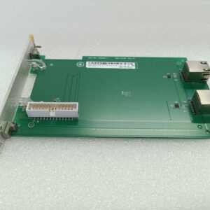
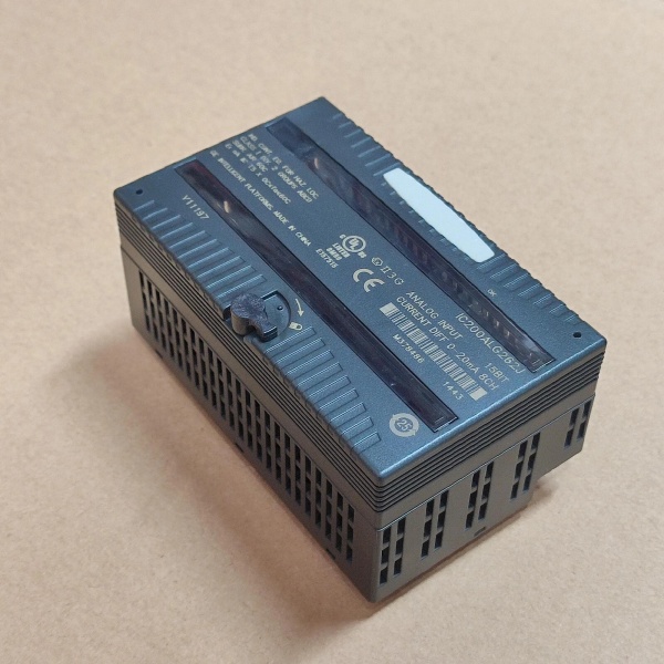
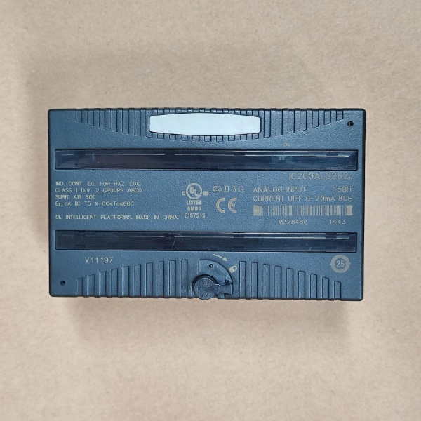
The GE IC200ALG262 is an 8-channel analog current input module within the GE VersaMax I/O platform, designed for Level 1 (Device) or Level 2 (Control) of the Purdue Model in industrial automation. It resides in control cabinets (mounted on a VersaMax baseplate) and serves as the bridge between field devices (e.g., pressure transmitters, temperature sensors) and higher-level controllers (e.g., GE VersaMax PLCs, ABB AC 800M DCS).
Upstream Signal Reception
Receives analog current signals (0–20 mA or 4–20 mA) from field devices via differential wiring (shielded twisted-pair cables). These signals represent process variables (e.g., pressure, temperature, flow) from the field.
Downstream Communication
Transmits digital data to the controller via the VersaMax backplane. The module uses a 15-bit ADC (analog-to-digital converter) to convert analog signals into digital values, which are then processed by the controller’s logic (e.g., PID loops, alarm generation).
Operational Advantages
-
High Precision: 15-bit resolution ensures accurate signal conversion (0.5 µA/count for 4–20 mA), critical for applications requiring tight process control (e.g., pharmaceutical manufacturing).
-
Noise Immunity: Differential wiring minimizes electromagnetic interference (EMI) from nearby motors or power lines, ensuring reliable signal transmission in harsh industrial environments.
-
Hot-Swap Capability: Allows technicians to replace the module without shutting down the system, minimizing downtime during maintenance.

GE IC200ALG331
Core Technical Specifications
|
Attribute
|
Specification
|
|---|---|
|
Product Type
|
8-Channel Analog Current Input Module
|
|
Part Number
|
IC200ALG262
|
|
Number of Channels
|
8 (differential)
|
|
Input Signal Range
|
0–20 mA / 4–20 mA (jumper configurable; default: 4–20 mA)
|
|
Resolution
|
15-bit (0.5 µA/count for 4–20 mA; 0.625 µA/count for 0–20 mA)
|
|
Update Rate
|
7.5 ms per channel
|
|
Input Impedance
|
100 Ω (current input)
|
|
Isolation
|
250V AC channel-to-channel (galvanic isolation)
|
|
Power Supply
|
5V DC from VersaMax backplane (200 mA max consumption)
|
|
Operating Temperature
|
-40°C to +70°C (-40°F to 158°F)
|
|
Storage Temperature
|
-40°C to +85°C (-40°F to 185°F)
|
|
Humidity
|
5–95% non-condensing
|
|
Dimensions (W×H×D)
|
~110 mm × 66.8 mm × 50 mm (4.3 in × 2.6 in × 2.0 in) (approximate)
|
|
Weight
|
~0.3 kg (0.66 lbs)
|
|
Certifications
|
CE, UL, RoHS (compliant with EU directives)
|
Customer Value & Operational Benefits
Enhanced Process Control Precision
The IC200ALG262’s 15-bit resolution and fast update rate (7.5 ms) enable real-time monitoring of process variables, reducing variability and improving product quality. For example, a chemical plant using the module reported a 25% reduction in batch-to-batch variation by improving temperature control.
Reduced Maintenance Costs
The module’s hot-swap design allows technicians to replace it in minutes without shutting down the system. A manufacturing plant using the IC200ALG262 cut maintenance downtime by 40% compared to traditional non-hot-swappable analog input modules.
Cost-Effective Integration
Compatible with GE’s VersaMax PLCs and third-party controllers (e.g., Siemens S7-1200), the IC200ALG262 eliminates the need for custom interfaces. A water treatment plant using the module saved $10,000 in integration costs by retaining its existing PLC infrastructure.
Field Engineer’s Notes (From the Trenches)
When installing the IC200ALG262, always use shielded twisted-pair cables—unshielded cables can pick up EMI from nearby motors or power lines, leading to signal distortion. I once saw a site where a technician used unshielded cables, resulting in a 15% error rate in pressure measurements. Switching to shielded cables eliminated the problem immediately.Another gotcha: verify the jumper configuration—the module’s default input range is 4–20 mA. If you need to use 0–20 mA, you must set the jumper on the carrier terminal. I’ve fixed countless “signal out of range” errors by forgetting to adjust the jumper.If the module’s “FAULT” LED illuminates, check the input signals—the module will report an open circuit fault if a sensor is disconnected. Use a multimeter to test the current signal from the sensor (e.g., 4–20 mA) and verify it matches the process variable.
Real-World Applications
-
Chemical Manufacturing:A chemical plant uses the IC200ALG262 to monitor the temperature of its reactor. The module receives 4–20 mA signals from a temperature transmitter and transmits digital data to a GE VersaMax PLC, which adjusts the flow of cooling water to maintain the reactor temperature within ±1°C.
-
Power Generation:A power plant uses the IC200ALG262 to monitor the pressure of its boiler feedwater pump. The module’s differential wiring minimizes EMI from the pump’s motors, ensuring accurate pressure measurements. The PLC uses this data to adjust the pump’s speed, improving energy efficiency by 10%.
-
Water Treatment:A water treatment plant uses the IC200ALG262 to monitor the pH of its effluent. The module receives 0–20 mA signals from a pH sensor and transmits data to a SCADA system, which triggers an alarm if the pH exceeds regulatory limits.
GE IC200ALG331
High-Frequency Troubleshooting FAQ
Q: What does the “FAULT” LED indicate on the GE IC200ALG262?
A: The red “FAULT” LED indicates a critical error, such as:
-
Open Circuit: A sensor is disconnected or the wiring is faulty (check the current signal with a multimeter);
-
Power Supply Issue: The VersaMax backplane is not supplying 5V DC (use a multimeter to test the backplane voltage);
-
Signal Out of Range: The input signal is outside the 0–20 mA/4–20 mA range (verify the sensor’s output).
Q: Can the IC200ALG262 be used with non-GE controllers?
A: Yes, the module’s digital output is compatible with most controllers (e.g., Siemens S7-1200, Allen-Bradley CompactLogix). However, you may need to configure the controller’s input module to match the IC200ALG262’s signal type (e.g., 4–20 mA).
Q: How do I configure the IC200ALG262’s input range?
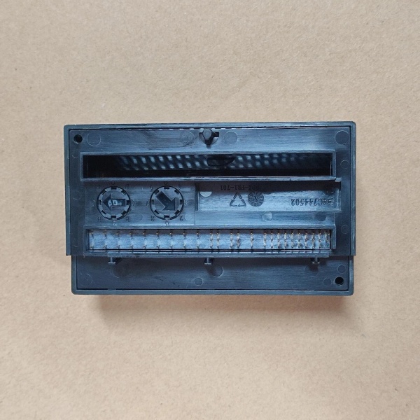
A: Use a jumper on the carrier terminal to select the input range:
-
4–20 mA: No jumper installed (default);
-
0–20 mA: Install a jumper between the “0–20 mA” pins.
Q: Why is the IC200ALG262’s signal unstable?
A: Check three things first:
-
Cables: Ensure the shielded twisted-pair cables are not damaged (check for cuts or breaks);
-
Grounding: Verify the shield is grounded at the source device (or the I/O module if the source cannot be grounded);
-
Sensor: Ensure the field device (e.g., sensor) is not faulty (test with a multimeter).
Commercial Availability & Pricing
Please note: The listed price is not the actual final price. It is for reference only and is subject to appropriate negotiation based on current market conditions, quantity, and availability.