Description
System Architecture & Operational Principle
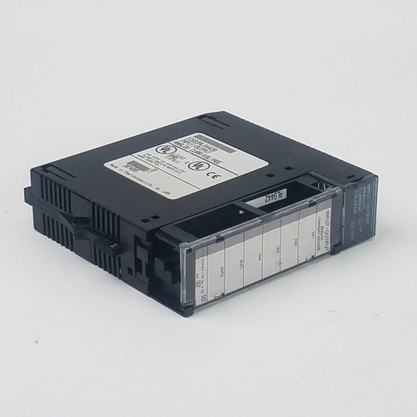
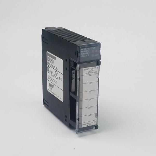
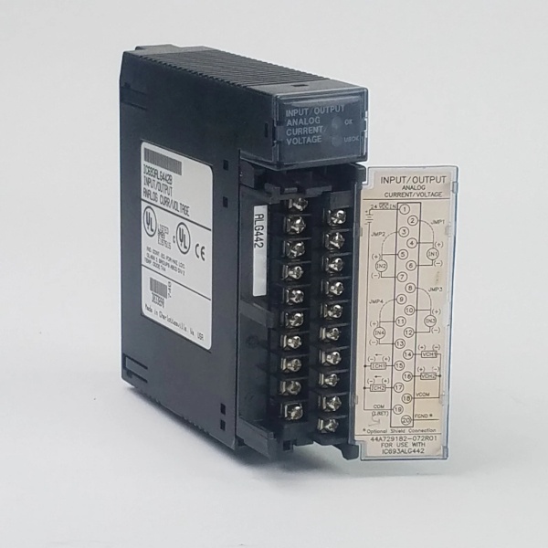
The IC693ALG442 is a core component of GE’s Series 90-30 PLC system, designed to occupy a slot in the PLC’s I/O rack (typically at Level 1 (Basic Control) or Level 2 (Supervisory Control) of the Purdue Model). It connects to field devices (e.g., pressure transmitters, control valves) via screw terminals, accepting analog input signals and transmitting analog output signals to actuators.
Operational Workflow:
-
Input Signal Acquisition: The 4 differential input channels use 12-bit ADCs to convert analog voltage/current signals (e.g., 4-20 mA from a pressure transmitter) into digital values. These values are stored in the PLC’s
%AIregisters for use in logic programs. -
Output Signal Generation: The 2 single-ended output channels use 12-bit DACs to convert digital values from the PLC’s
%AQregisters into analog voltage/current signals (e.g., 0-10 VDC to a control valve). -
Isolation & Protection: The module features 1500 VAC RMS optical isolation between field wiring and the PLC logic, preventing ground loops and voltage spikes from damaging the CPU.
-
Communication: The module communicates with the PLC CPU over the backplane, providing status information (e.g., module health, open-wire faults) to support real-time process control.
Architectural Advantage:
The IC693ALG442’s mixed I/O design reduces the number of slots required in the PLC rack, simplifying system architecture. Its high isolation rating ensures reliable operation in harsh industrial environments, while its configurable input/output ranges adapt to diverse field devices.

IC693ALG442
Core Technical Specifications
-
Input Channels: 4 differential (0-10 VDC, ±10 VDC, 0-20 mA, 4-20 mA, 4-20 mA Enhanced)
-
Output Channels: 2 single-ended (0-10 VDC, ±10 VDC, 0-20 mA, 4-20 mA)
-
Resolution: 12-bit (input/output)
-
Accuracy: ±0.25% full scale (input, 25°C); ±0.1% full scale (output, 25°C)
-
Update Rate: 8 ms (input channels); 4 ms (output channels)
-
Isolation: 1500 VAC RMS (field-to-logic)
-
Power Consumption: 95 mA from +5 VDC backplane; 129 mA from +24 VDC external supply
-
Input Impedance: 250 Ω (current mode); 1 MΩ (voltage mode)
-
Output Load: 0-850 Ω (current mode); ≥2 kΩ (voltage mode)
-
Operating Temperature: 0°C to 60°C (32°F to 140°F)
-
Certifications: UL, CE, RoHS
Customer Value & Operational Benefits
Space & Cost Efficiency
The IC693ALG442’s 4-input/2-output design reduces the number of I/O slots required in the PLC rack, saving valuable cabinet space and minimizing hardware costs. This is critical for compact control panels in industries like food processing or packaging.
Flexible Signal Compatibility
The module’s configurable input/output ranges (0-10 VDC, ±10 VDC, 0-20 mA, 4-20 mA) adapt to diverse field devices, from pressure transmitters (4-20 mA) to control valves (0-10 VDC). This eliminates the need for multiple module types, reducing inventory costs.
Reliable Isolation & Protection
The 1500 VAC RMS optical isolation protects the PLC from field-side noise and voltage spikes, reducing the risk of CPU damage and ensuring stable operation in harsh industrial environments (e.g., near motors or drives).
Real-Time Process Control
The fast update rates (8 ms input, 4 ms output) ensure real-time signal acquisition and control, critical for applications like chemical dosing or temperature regulation where small delays can impact product quality.
Field Engineer’s Notes (From the Trenches)
When wiring the IC693ALG442, always use twisted/shielded instrumentation cable for field connections—unshielded cable will pick up EMI, causing erratic readings. I once saw a site use regular Ethernet cable, and the 4-20 mA signal from a flow meter fluctuated by 10%, leading to incorrect pump control.Double-check the input/output range configuration in the PLC software (e.g., Logicmaster 90-30) before commissioning. A misconfigured range (e.g., 0-10 VDC instead of 4-20 mA) will saturate the field device, causing damage or incorrect operation. I always label each channel’s range on the terminal block (e.g., “Ch1: 4-20 mA – Pressure Sensor”) to avoid confusion.Test the open-wire detection (in current mode) during commissioning. Disconnect a sensor cable and verify that the PLC receives a fault message—this ensures the feature works before putting the system into operation.
Real-World Applications
-
Chemical Processing: Monitors 4 pressure transmitters (4-20 mA) in a reactor using the input channels. The PLC uses this data to adjust coolant valves (0-10 VDC) via the output channels, maintaining reaction temperature within a ±0.5°C band.
-
Water Treatment: Uses 4 level sensors (0-10 VDC) to monitor storage tanks. The PLC controls 2 pumps (4-20 mA) via the output channels, preventing overflows and ensuring consistent water supply.
IC693ALG442
High-Frequency Troubleshooting FAQ
Q: How do I configure the input/output ranges for the IC693ALG442?
A: Use the PLC programming software (e.g., Logicmaster 90-30) to select the desired range (0-10 VDC, ±10 VDC, 0-20 mA, 4-20 mA) for each channel. The module does not have physical jumpers—configuration is done via software.
Q: What does an “open-wire fault” mean?
A: An open-wire fault occurs when the module detects a break in the current loop (e.g., broken cable, disconnected sensor). The PLC will receive a fault message for the affected channel, allowing the operator to take corrective action.
Q: Can I replace the IC693ALG442 with a newer module?
A: Yes—consider the Emerson IC694ALG442 (for Series 90-70 PLCs) or IC695ALG442 (for RX3i systems). Both offer 16-bit resolution and faster update rates (1 ms per channel). Verify the new module’s footprint and power requirements before swapping.
Q: How do I test the module’s accuracy?
A: Use a precision voltage source (e.g., 5 VDC reference) or current source (e.g., 4-20 mA calibrator) to apply a known signal to a channel. Read the digital value from the PLC and compare it to the expected count (e.g., 5 VDC should be 2048 counts at 0-10 VDC). If the error exceeds ±0.25% of full scale, replace the module.
Commercial Availability & Pricing
Please note: The listed price is not the actual final price. It is for reference only and is subject to appropriate negotiation based on current market conditions, quantity, and availability.