Description
3. Key Technical Specifications
|
Parameter
|
Specification
|
|---|---|
|
Cable Length
|
3 meters (10 feet)
|
|
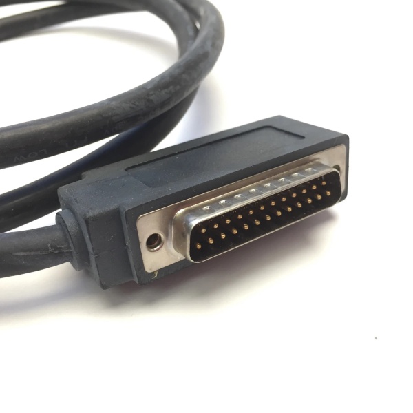
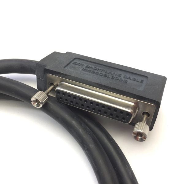
Connector Type
|
One end: 24-pin right-angle D-type (Fujitsu FCN-365S024-AU)
Other end: Pre-stripped/tinned wires |
|
Current Rating
|
1.2 amps per conductor (max)
|
|
Compatibility
|
Series 90-30 32-point I/O modules (e.g., IC694MDL654, IC694MDL752, IC694MDL753)
|
|
Connector Depth
|
2 inches (51 mm) from module front panel (requires cabinet clearance)
|
|
Wire Gauge
|
24 AWG
|
|
Shielding
|
Unshielded (designed for internal cabinet use)
|
|
Operating Temperature
|
-20°C to +60°C (-4°F to 140°F)
|
|
Certifications
|
UL, CE
|
IC693CBL300
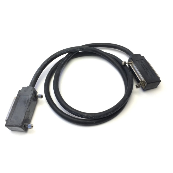
4. Product Introduction
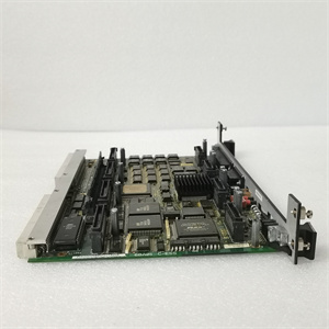
The GE IC693CBL327 is a purpose-built I/O interface cable for GE Series 90-30 PLC systems, designed to connect 32-point high-density I/O modules to field devices. Its 24-pin right-angle connector (Fujitsu FCN-365S024-AU) plugs into the I/O module, while the pre-stripped wire ends simplify field wiring to terminal blocks (e.g., IC693ACC337).
Core Value Proposition:
-
Space Efficiency: The right-angle connector reduces front-panel clearance requirements by up to 40% compared to straight connectors, making it ideal for compact cabinet designs.
-
Reliability: Pre-stripped and tinned wires ensure consistent signal integrity, while the 1.2A per conductor rating supports high-current applications (e.g., relay outputs, solenoids).
-
Compatibility: Direct replacement for discontinued OEM cables, with verified pinout alignment for Series 90-30 32-point modules.
This cable is a critical component for industrial automation systems, enabling seamless communication between PLCs and field devices in applications like machinery control, process automation, and robotics.
5. Firmware/Software Versions & Upgrade Notes
-
Configuration Tools: No firmware or software updates required for the cable itself. Configuration is handled via the PLC’s programming software (e.g., LogicMaster 90-30, VersaPro) for I/O mapping.
-
Compatibility: Works with all Series 90-30 CPUs (e.g., IC693CPU331, IC693CPU350) and 32-point I/O modules. Ensure the PLC’s backplane has sufficient power to support the connected I/O modules (calculate 1.2A per conductor for 32 points).
-
Upgrade Risks: None for the cable. However, upgrading PLC firmware may require revalidating I/O configurations in the programming software.

IC693CBL300
6. Frequently Asked Questions (FAQ)
1. What is the GE IC693CBL327 used for?
It connects Series 90-30 PLCs to 32-point high-density I/O modules (e.g., IC694MDL752) for field device wiring. The right-angle connector plugs into the I/O module, and the pre-stripped wires connect to terminal blocks.
2. Can I use this cable with non-32-point I/O modules?
No. The 24-pin connector and pinout are specific to Series 90-30 32-point modules. For 16-point or analog modules, use the appropriate cable (e.g., IC693CBL329 for 16-point modules).
3. What is the maximum current per conductor?
1.2 amps per conductor (24 AWG wire). For 32-point modules, this supports up to 38.4A total current (1.2A x 32), which is sufficient for most industrial loads.
4. Is this cable shielded?
No. It is designed for internal cabinet use, where EMI is minimized by the PLC’s chassis. For outdoor or high-EMI environments, use a shielded cable (e.g., IC693CBL330) with additional grounding.
5. What is the warranty for New Surplus units?
12 months, covering manufacturing defects (e.g., broken connectors, shorted wires). Suppliers may offer extended warranties (+15% cost for 24 months).
6. How do I terminate the pre-stripped wires?
Use a terminal block (e.g., IC693ACC337) with screw terminals. Strip 0.25 inches (6.35 mm) of insulation and insert the wire into the terminal. Tighten the screw to 5 in-lbs (0.56 N·m) to ensure a secure connection.
7. Can I use this cable for analog I/O?
Yes, but ensure the analog module’s voltage (e.g., ±10V DC) matches the cable’s insulation rating (600V AC/DC). Use shielded cable for analog signals to minimize noise.