Description
Product Introduction
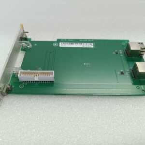
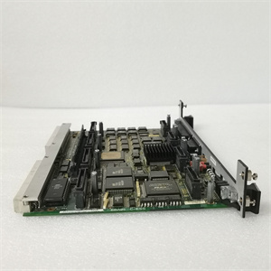
The GE IC693DNM200 serves as the traffic controller for DeviceNet networks—I’ve deployed these in automotive assembly lines where coordinating dozens of sensors and actuators demands precise timing. This single-slot module transforms Series 90-30 PLCs into DeviceNet masters, managing up to 63 slave devices across three selectable baud rates .Honestly, the dual-mode operation (master/slave) provides flexibility, though most installations use it as a master. The 500Kb/s maximum baud rate handles real-time control demands, but network length constraints apply—DeviceNet spec limits cable runs to 500 meters at 125Kb/s, dropping to 100 meters at 500Kb/s .
Key Technical Specifications
| Parameter | Value |
|---|---|
| Module Type | Single-Slot DeviceNet Master Module |
| Communication Protocol | DeviceNet (ODVA compliant) |
| Baud Rates | 125Kb/s, 250Kb/s, 500Kb/s (selectable) |
| Network Capacity | 63 slave devices maximum, 126 I/O connections total |
| I/O Data Capacity | 255 bytes input/output per slave, 3,972 bytes total system capacity |
| Power Supply | 12-24V DC (positive logic) |
| Output Current | 0.5A per point, 3A maximum per common group |
| Response Time | ≤0.5ms for digital inputs |
| Operating Temperature | 0°C to 60°C (32°F to 140°F); storage: -40°C to 85°C |
| Dimensions | 115 mm × 46 mm × 23 mm (4.53″ × 1.81″ × 0.91″) |
| Weight | 150 g (5.3 oz) |
| Protection Rating | IP20 |
| Certifications | UL508, C-UL, CE |
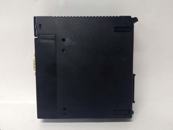
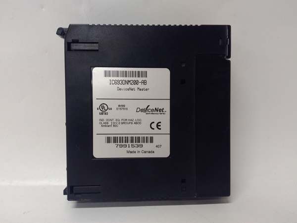
GE IC693DNM200
Quality Control Process (SOP Transparency)
Here’s how we verify the GE IC693DNM200. We use a dedicated DeviceNet test network with multiple slave simulators and a Fluke 123B scope meter.
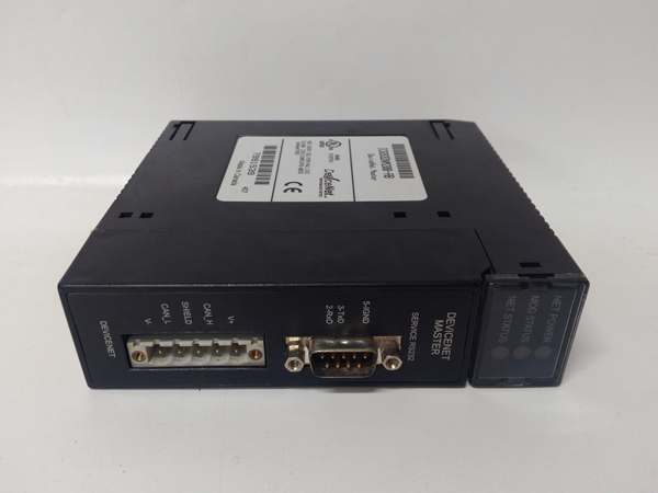
- Incoming Verification: Trace serials against OEM lists, inspect 9-pin D-sub DeviceNet connector for bent pins, verify LED indicators (PWR, NET, MOD), audit accessories (none included).
- Live Functional Test: Install in Series 90-30 test rack, power-on self-check, configure baud rates (125K/250K/500K), connect to 5 simulated slave devices, test explicit messaging and I/O polling, run 48 hr network stability test.
- Electrical Parameter Test: Megger insulation at 500 V (>10 MΩ), verify DC input range (12-24V), measure quiescent current (typically 85 mA at 24V), check DeviceNet termination resistance (121Ω ±1%).
- Firmware Verification: Read firmware version via RS-232 service port, document configuration parameters, test UCMM (Unconnected Message Manager) functionality.
- Final QC & Packaging: Inspector signs off, seal in anti-static bag with desiccant, bubble wrap + double-walled carton, apply QC Passed label with date and baud rate test results.
GE IC693DNM200
Replacement Pitfall Guide (Field Engineer’s Warnings)
Swapping this DeviceNet master introduces specific network risks. Keep these five points in mind and you’ll eliminate roughly 90% of commissioning headaches.
- ❗ Baud Rate Mismatch: The module defaults to 125Kb/s. Mismatched baud rates cause complete network failure. Document existing network speed before removal—check all slaves support the selected rate .
- ❗ MAC ID Conflicts: Each DeviceNet device requires a unique MAC ID (0-63). Duplicate MAC IDs create communication chaos. Verify no other device uses MAC ID 0 (typically reserved for the master). Case: New module shipped with MAC ID 0, but existing scanner used ID 0—network collapsed.
- ❗ Power Supply Insufficiency: DeviceNet networks require separate 24V power. Undersized supplies cause voltage drop and intermittent faults. Calculate total network current: slaves + termination + cable losses. Added 20 slaves? Network drew 4A; 24V/2A supply caused 3V drop at farthest node.
- ❗ Termination Resistor Omission: DeviceNet requires exactly two 121Ω termination resistors. Missing resistors cause signal reflections and data corruption. Install one at each physical network end—not at the master. Network showed intermittent errors; missing end resistor was the culprit.
- ❗ Grounding Neglect: DeviceNet shield must be grounded at one point only. Multiple ground points create ground loops and noise. Use the master’s ground terminal, isolate shield at all other locations. Hum interference disappeared after removing secondary shield ground.