Description
Product Overview
Technical Specifications
| Parameter Name | Parameter Value |
|---|---|
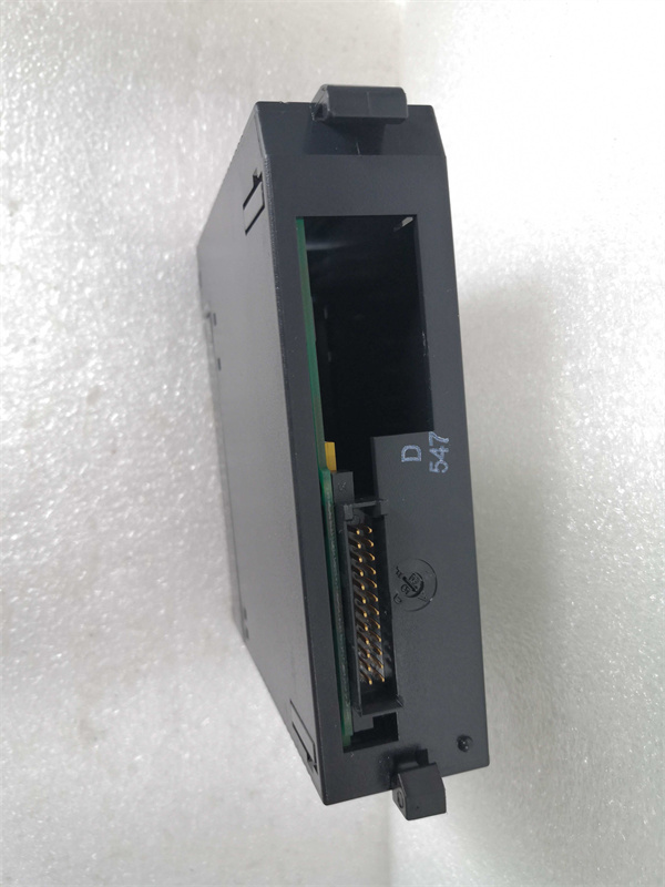
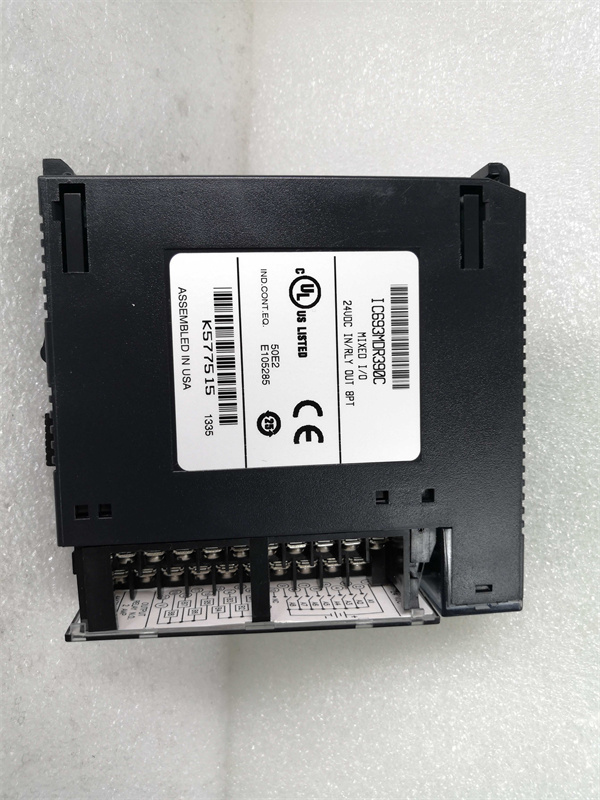
| Product Model | IC693MDR390 |
| Manufacturer | General Electric |
| Product Type | Discrete Input/Output Module |
| Input Voltage Range | – 30 to + 32 VDC |
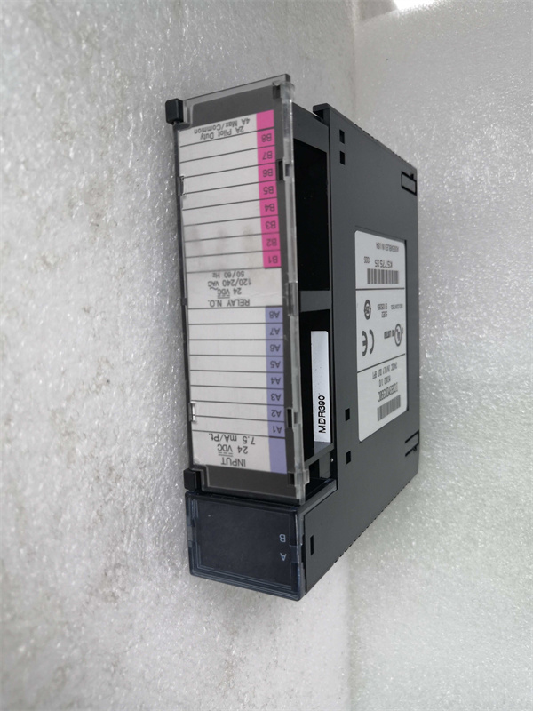
| Rated Input Voltage | 24 VDC |
| Input Current | 7.5 mA at rated voltage |
| On – State Voltage (Input) | 15 to 32 VDC |
| Off – State Voltage (Input) | 0 to 5 VDC |
| On – State Current (Input) | 4 mA (minimum) |
| Off – State Current (Input) | 1.5 mA (maximum) |
| On/Off Response Time (Input) | 7 ms (typical) |
| Output Voltage Range | 5 to 30 VDC, 5 – 250 VAC (50/60 Hz) |
| Nominal Output Voltage | 24 VDC; 120/240 VAC |
| Maximum Load per Output | 2 amps |
| Maximum Load per Common | 4 amps |
| Output Isolation | 1500 volts rms between field and logic side; 500 volts rms between output groups |
| On/Off Response Time (Output) | 15 ms (typical) |
| Internal Power Consumption (All I/O Active) | 80 mA |
| Internal Power Consumption (All Outputs Energized) | 70 mA |
| Backplane Current Draw (All I/O Active) | 80 mA |
| Backplane Current Draw (Outputs Energized) | 70 mA |
| Module Type | Single – slot module |
| Installation | Can be installed in any I/O slot of the Series 90 – 30 baseplate |
| Isolation (Field – Logic) | 1500 volts rms |
| Resistive Load (Max per Output) | 2 amps |
| Lamp/Solenoid Load (Max) | 0.6 amps |
| Maximum Inrush Current | 5 amps |
IC693MDR390
Main Features and Advantages
High Isolation and Efficient Power Consumption: Boasting 1500 volts rms isolation between the field and logic side, and 500 volts rms between output groups, this module offers excellent protection against electrical interference. This isolation not only safeguards the module itself but also the connected devices. In terms of power consumption, it is designed to be efficient, with internal power consumption of 80 mA when all I/O are active and 70 mA when all outputs are energized, ensuring cost – effective operation in long – term use.
Clear Status Indicators: Equipped with LED indicators for each input and output point, the IC693MDR390 provides real – time status monitoring. The two horizontal rows of eight green LEDs, with the top row for input points (labeled A1 – 8) and the bottom row for relay output points (labeled B1 – 8), make it easy for operators to quickly identify the on/off status of each channel. This feature significantly simplifies troubleshooting, reducing downtime in case of issues.
Application Field
Manufacturing Industry: In manufacturing plants, the GE IC693MDR390 is extensively used in production line control. For example, it can be connected to proximity sensors on conveyor belts to detect the presence of products. When a product is sensed, the module can then activate a relay output to control the operation of a robotic arm for sorting or packaging. In a precision – machining factory, the module’s inputs can be connected to limit switches on machine tools, and its outputs can control the solenoids that operate tool changers, ensuring accurate and efficient machining processes.
Industrial Automation Systems: In large – scale industrial automation setups, this module plays a vital role. It can be used to interface between different components of a control system. For instance, in a chemical plant, the module’s inputs can receive signals from temperature and pressure sensors, and its outputs can control the opening and closing of valves based on the sensor readings. This helps in maintaining the optimal conditions for chemical reactions, ensuring product quality and plant safety.
Power Generation Facilities: In power plants, the IC693MDR390 can be used to monitor and control auxiliary equipment. It can receive input signals from sensors that detect the status of pumps, fans, and generators. Based on these inputs, the module can then control the relays that start or stop these devices, contributing to the smooth operation of the power generation process.
IC693MDR390
Related Products
- GE IC693MDL740: This is another input/output module in the GE Fanuc Series 90 – 30. While the IC693MDR390 has a combination of discrete inputs and relay outputs, the IC693MDL740 might have different input/output configurations, such as more or fewer channels, or different types of inputs (e.g., only digital inputs). It can be used in applications where a different input/output setup is required.
- GE 90 – 30 Baseplate: The IC693MDR390 is designed to be installed on the 90 – 30 baseplate. The baseplate provides the electrical and mechanical connection for the module and other components in the PLC system. Different sizes and versions of the baseplate can be selected depending on the number of modules needed in the system and the specific application requirements.
- GE Proficy Logic Developer: This is the programming software used to configure and program the IC693MDR390 within the PLC system. It offers a user – friendly interface and supports multiple programming languages like ladder diagram (LDI), instruction list (IL), and structured text (ST), allowing engineers to customize the module’s functionality according to the needs of the industrial application.
- GE Fanuc Series 90 – 70 PLC: The Series 90 – 70 PLC is a more advanced system in GE’s lineup. Although the IC693MDR390 is designed for the Series 90 – 30, in some cases, parts of the Series 90 – 30 system, including this module, might be used in combination with the Series 90 – 70 in hybrid setups or during system upgrades, where the 90 – 70 provides higher – level control and the 90 – 30 components handle specific local I/O tasks.
- GE Industrial Sensors: These sensors, such as proximity sensors and limit switches, are often connected to the inputs of the IC693MDR390. Different types of sensors with varying detection ranges and accuracies can be used depending on the application. For example, in a high – precision manufacturing process, a more accurate proximity sensor might be paired with the module to ensure precise detection of object positions.
Installation and Maintenance
Maintenance recommendations: Regularly inspect the IC693MDR390 for any signs of physical damage, such as cracks in the casing or loose connections. Monitor the LED indicators to check the normal operation of input and output channels. Use appropriate electrical testing equipment to verify the voltage levels at the inputs and outputs. If any abnormal behavior is detected, such as incorrect on/off status of channels or excessive heat generation, refer to the troubleshooting guide in the user manual. Clean the module gently to remove dust that could potentially affect its performance. In case of complex issues, contact GE’s technical support team for assistance.