Description
System Architecture & Operational Principle
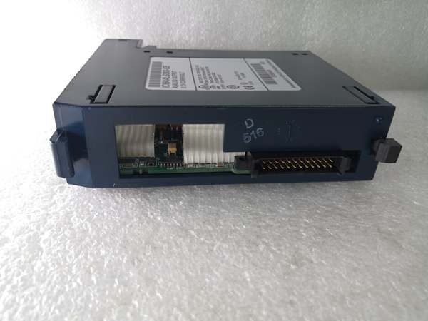
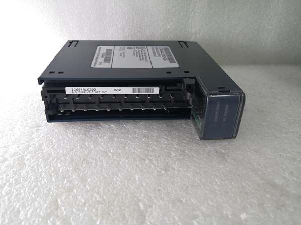
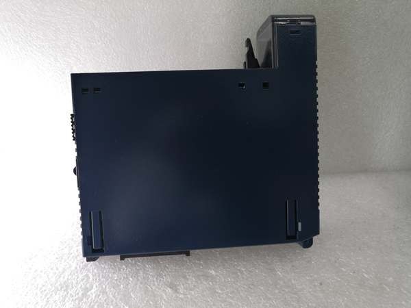
The GE IC694ALG392 is an 8-channel analog output module within the GE Fanuc PACSystems RX3i series, designed for Level 1 (Device) or Level 2 (Control) of the Purdue Model in industrial automation. It resides in control cabinets (mounted on a RX3i CPU baseplate) and acts as the bridge between higher-level controllers (e.g., GE RX3i PLCs) and field devices (e.g., control valves, motor drives, hydraulic actuators).
Upstream Signal Reception
Receives digital control signals from the RX3i PLC via the backplane. These signals represent desired setpoints (e.g., valve opening percentage, motor speed) generated by the controller’s logic (e.g., PID loops, sequence control).
Downstream Communication
Converts digital signals to analog current/voltage signals using a 15–16 bit digital-to-analog converter (DAC). The analog signals are transmitted to field devices via single-ended wiring (screw terminals or pre-wired cables). For example:
-
A 4–20 mA signal might control a control valve’s position (4 mA = fully closed, 20 mA = fully open).
-
A 0–10 V signal might adjust a variable frequency drive (VFD)’s speed (0 V = stop, 10 V = maximum speed).
Operational Advantages
-
High Flexibility: Supports multiple signal types (current/voltage) and ranges, adapting to diverse field devices without requiring additional converters.
-
Fast Response: 8 ms update rate ensures real-time control of dynamic processes (e.g., chemical reactor temperature regulation, conveyor belt speed adjustment).
-
Rugged Reliability: Wide operating temperature range (-40°C to +70°C) and 250V AC channel-to-backplane isolation make it suitable for harsh industrial environments (e.g., power plants, chemical refineries).

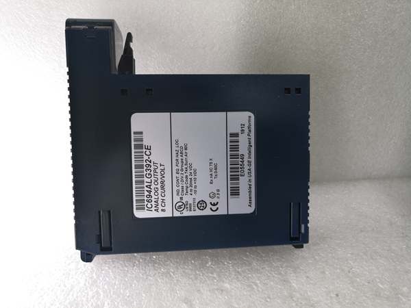
GE IC694ALG392
Core Technical Specifications
|
Attribute
|
Specification
|
|---|---|
|
Product Type
|
8-Channel Analog Output Module
|
|
Part Number
|
IC694ALG392
|
|
Number of Channels
|
8 (single-ended)
|
|
Output Signal Range
|
Current: 0–20 mA / 4–20 mA; Voltage: 0–10 V / ±10 V (configurable per channel)
|
|
Resolution
|
15–16 bit (depends on output range: 0.5 µA/count for 4–20 mA; 0.3125 mV/count for ±10 V)
|
|
Update Rate
|
8 ms per channel (max)
|
|
Output Impedance
|
< 1 Ω (current output); > 10 MΩ (voltage output)
|
|
Isolation
|
250V AC (channel-to-backplane); 500V AC (channel-to-ground) (per )
|
|
Power Supply
|
5V DC from RX3i backplane (110 mA max); 24V DC external (315 mA max)
|
|
Operating Temperature
|
-40°C to +70°C (-40°F to 158°F)
|
|
Storage Temperature
|
-40°C to +85°C (-40°F to 185°F)
|
|
Humidity
|
5–95% non-condensing
|
|
Dimensions (W×H×D)
|
~115 mm × 100 mm × 25 mm (4.5 in × 3.9 in × 1.0 in) (approximate)
|
|
Weight
|
~0.3 kg (0.66 lbs)
|
|
Certifications
|
CE, UL, CSA (compliant with EU/US/Canadian standards)
|
Customer Value & Operational Benefits
Enhanced Process Control Precision
The IC694ALG392’s 15–16 bit resolution and fast update rate (8 ms) enable precise control of field devices, reducing process variability and improving product quality. For example, a food processing plant using the module to control oven temperature reported a 15% reduction in product defects due to more accurate heat regulation.
Reduced Downtime & Maintenance Costs
The module’s hot-swap design (compatible with RX3i baseplates) allows technicians to replace it without shutting down the system. A water treatment plant using the IC694ALG392 cut maintenance downtime by 30% compared to traditional non-hot-swappable analog output modules.
Cost-Effective Scalability
As part of the RX3i PACSystem family, the IC694ALG392 integrates seamlessly with other GE modules (e.g., digital I/O, communication modules), eliminating the need for custom interfaces. A manufacturing plant expanded its production line using the module and saved $8,000 in integration costs by retaining its existing PLC infrastructure.
Field Engineer’s Notes (From the Trenches)
When configuring the IC694ALG392, always verify the output range—the module defaults to 4–20 mA, but if you need to use 0–20 mA or voltage ranges, you must adjust the jumper settings on the carrier terminal. I once saw a site where a technician forgot to change the jumper, resulting in a valve only opening halfway (since 4 mA = 0% instead of 0 mA).Another tip: use shielded twisted-pair (STP) cables for analog outputs—unshielded cables can pick up electromagnetic interference (EMI) from nearby motors or power lines, leading to signal distortion. A chemical plant fixed a “valve hunting” issue (constant small adjustments) by switching to STP cables.If the module’s “FAULT” LED illuminates, check the external power supply first— the module requires a stable 24V DC external supply (20–30V range). I’ve seen cases where a faulty power supply (outputting 18V DC) caused the module to enter a fault state. Use a multimeter to test the external power supply voltage before replacing the module.GE IC694ALG392
Real-World Applications
-
Chemical Manufacturing:A chemical plant uses the IC694ALG392 to control the flow of reactants into a reactor. The module receives 4–20 mA signals from the RX3i PLC (based on pH sensor feedback) and adjusts the valve opening to maintain the desired pH level (±0.1 pH).
-
Power Generation:A power plant uses the IC694ALG392 to control the speed of its coal conveyor belt. The module sends 0–10 V signals to a VFD, adjusting the belt speed to match the boiler’s fuel demand (reducing energy consumption by 12%).
-
Water Treatment:A water treatment plant uses the IC694ALG392 to control the dosage of chlorine into the effluent. The module receives 4–20 mA signals from a flow meter and adjusts the chlorine injection valve to ensure compliance with environmental regulations (±5% accuracy).
High-Frequency Troubleshooting FAQ
Q: What does the “FAULT” LED indicate on the GE IC694ALG392?
A: The red “FAULT” LED indicates a critical error, such as:
-
Power Supply Failure: The external 24V DC supply is missing or unstable (check with a multimeter);
-
Open Circuit: A field device (e.g., valve) is disconnected or the wiring is faulty (use a multimeter to test the current signal);
-
Module Fault: The internal DAC or power supply is faulty (replace the module).
Q: Can the IC694ALG392 be used with non-GE controllers?
A: Yes, the module’s digital input is compatible with most controllers (e.g., Siemens S7-1200, Allen-Bradley CompactLogix). However, you may need to configure the controller’s output module to match the IC694ALG392’s signal type (e.g., 4–20 mA).
Q: How do I configure the output range on the IC694ALG392?
A: Use GE’s Proficy Machine Edition software to configure the output range:
-
Open Proficy Machine Edition: Launch the software and connect to the RX3i PLC;
-
Select the IC694ALG392: Navigate to the “I/O Configuration” tab and select the module;
-
Set Output Range: Choose “0–20 mA,” “4–20 mA,” “0–10 V,” or “±10 V” for each channel;
-
Save Configuration: Click “Save” to apply the changes to the module’s memory.
Q: Why is the IC694ALG392’s signal unstable?
A: Check three things first:
-
Cables: Ensure the STP cables are not damaged (check for cuts or breaks);
-
Grounding: Verify the shield is grounded at the source device (or the I/O module if the source cannot be grounded);
-
Field Device: Ensure the field device (e.g., valve) is not faulty (test with a multimeter).
Commercial Availability & Pricing
Please note: The listed price is not the actual final price. It is for reference only and is subject to appropriate negotiation based on current market conditions, quantity, and availability.