
Description
Product Introduction
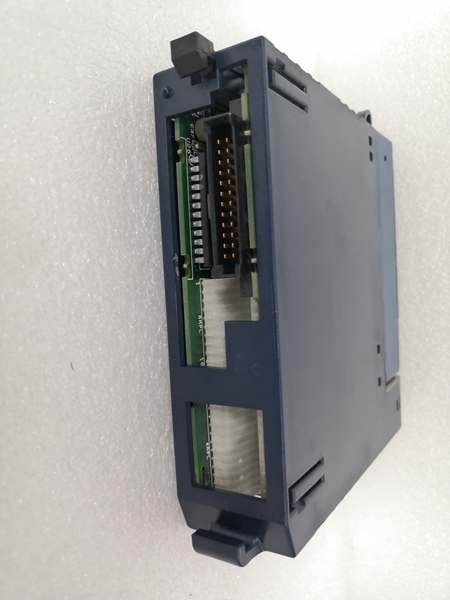
The “C” suffix typically indicates a specific revision or regional variant—functionally identical to the base IC694BEM331. This unit bridges PACSystems RX3i controllers to legacy Genius serial bus networks. It handles real-time data exchange with distributed I/O, VersaMax, and older GE systems.Technical difference? Honestly, the “C” usually means minor firmware or component revisions. Same 128-byte per-device data capacity, same 32-device maximum, same 2000V isolation. The unit maintains backward compatibility while supporting modern configuration tools. Check your existing system’s firmware version if mixing revisions.
Key Technical Specifications
| Parameter | Value |
|---|---|
| Maximum Devices | 32 devices (16 at 38.4Kbaud) |
| Data Exchange | 128 bytes per device + 128 bytes global data |
| Baud Rates | 153.5Kbaud (standard/extended), 76.8Kbaud, 38.4Kbaud |
| Bus Termination | 75, 100, 120, or 150Ω resistors (both ends required) |
| Maximum Cable Length | 7,800 ft at 38.4Kbaud, 2,000 ft at 153.6Kbaud standard |
| Isolation Rating | 2,000V Hi-Pot, 1,500V transient common mode rejection |
| Power Consumption | 300 mA @ +5 VDC |
| Maximum Modules per System | 8 |
| Cable Types | Twisted-pair, Twinax, or Fiber optic |
| LED Indicators | OK (module status), COM (bus communication) |
| Compatibility | PACSystems RX3i, Series 90-30, Series 6, Genius I/O, VersaMax |
| Configuration Software | Proficy Machine Edition |

GE IC694BEM331
Quality Control Process (SOP Transparency)
Testing bus controllers requires verifying both hardware functionality and communication protocols.
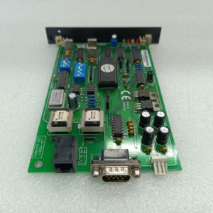
- Incoming Verification: Serial validation against Emerson’s database, visual inspection of the 9-pin D-sub connector and termination resistor jumpers. We check for any physical damage to the isolation barrier components.
- Communication Test: Using an RX3i test rack with CPU315, we connect the module to a Genius I/O test station with simulated devices. We verify data exchange at all three baud rates (38.4K, 76.8K, 153.5K) using Proficy Machine Edition. The OK LED must be steady green, COM LED must be steady during normal operation.
- Isolation Test: Hi-Pot tester applies 2,000V DC between field terminals and backplane for 60 seconds—must show no breakdown. Transient suppression is verified with a surge generator applying 1,500V spikes.
- Termination Verification: We test with various termination resistors (75Ω, 100Ω, 120Ω, 150Ω) to ensure the module correctly terminates the bus. Improper termination causes signal reflections that corrupt data—this is critical for long cable runs.
- Final QC & Packaging: QC inspector signs off, termination jumpers set to factory default (open), module sealed in anti-static bag with desiccant. QC label shows “All baud rates verified, 2,000V isolation passed.”

GE IC694BEM331
Replacement Pitfall Guide (Field Engineer’s Warnings)
Genius bus systems are temperamental—get one thing wrong and the whole network goes down.
- ❗ Termination Resistors Are Mandatory at Both Ends: The bus requires 75-150Ω resistors at both physical ends of the cable. Not just one end—both. I’ve seen networks with intermittent communication because someone terminated only the controller end. Measure resistance between Data+ and Data- at each end; should read 37.5-75Ω (half the resistor value since they’re in parallel).
- ❗ Baud Rate Must Match All Devices: Every device on the Genius bus must run at the same baud rate. If you replace this module and configure it for 153.5Kbaud while field devices are set to 38.4Kbaud, nothing communicates. Record the existing baud rate before swapping—it’s often marked on the old module’s label.
- ❗ Cable Length Depends on Baud Rate: Maximum distance shrinks as speed increases: 7,800 feet at 38.4Kbaud, but only 2,000 feet at 153.6Kbaud standard. Exceed these distances and you’ll get CRC errors. Measure your actual cable run—don’t guess.
- ❗ Global Data Configuration is Non-Intuitive: The 128-byte global data exchange needs proper configuration in Proficy Machine Edition. If not set up correctly, devices won’t share status information. This isn’t plug-and-play—you need to map the global data blocks in your program.
- ❗ No Hot-Swap Capability: Unlike some modern bus systems, this controller requires a power cycle after installation. The CPU won’t recognize a newly inserted module until you cycle power. Plan for downtime when replacing this unit.
Keep these five points in mind and you’ll eliminate roughly 90% of rework.