Description
Product Introduction
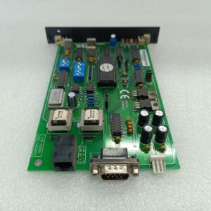
The “LTC” suffix denotes a specific variant—functionally identical to base IC694BEM331. This controller connects PACSystems RX3i systems to Genius serial bus networks, handling real-time data exchange with distributed I/O.Differentiation: The “LTC” typically indicates firmware or component revisions for specific regional or application requirements. Same 128-byte per-device data capacity, same 32-device maximum, same 2000V isolation. Verify compatibility with existing system firmware if mixing revisions.
Key Technical Specifications
| Parameter | Value |
|---|---|
| Maximum Devices | 32 devices (16 at 38.4Kbaud) |
| Data Exchange | 128 bytes per device + 128 bytes global data |
| Baud Rates | 153.5Kbaud (standard/extended), 76.8Kbaud, 38.4Kbaud |
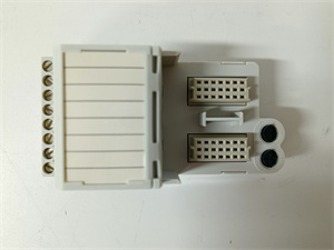
| Bus Termination | 75, 100, 120, or 150Ω resistors (both ends required) |
| Maximum Cable Length | 7,800 ft at 38.4Kbaud, 2,000 ft at 153.6Kbaud standard |
| Isolation Rating | 2,000V Hi-Pot, 1,500V transient common mode rejection |
| Power Consumption | 300 mA @ +5 VDC |
| Maximum Modules per System | 8 |
| Cable Types | Twisted-pair, Twinax, or Fiber optic |
| LED Indicators | OK (module status), COM (bus communication) |
| Compatibility | PACSystems RX3i, Series 90-30, Series 6, Genius I/O, VersaMax |
| Configuration Software | Proficy Machine Edition |

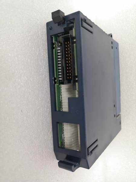
GE IC694BEM331
Quality Control Process (SOP Transparency)
Testing follows standard bus controller protocol with variant-specific firmware checks.
- Incoming Verification: Serial validation against Emerson’s database, visual inspection of 9-pin D-sub connector and termination resistor jumpers. Check for “LTC” marking on PCB.
- Communication Test: Using RX3i test rack with CPU315, connect to Genius I/O test station. Verify data exchange at all three baud rates using Proficy Machine Edition. OK LED steady green, COM LED steady during operation.
- Isolation Test: Hi-Pot tester applies 2,000V DC between field terminals and backplane for 60 seconds—no breakdown. Transient suppression verified with 1,500V surge generator.
- Termination Verification: Test with various termination resistors (75Ω, 100Ω, 120Ω, 150Ω) to ensure proper bus termination. Signal integrity checked with oscilloscope on long cable simulation.
- Final QC & Packaging: QC inspector signs off, termination jumpers set to factory default (open), module sealed in anti-static bag with desiccant. QC label shows “LTC variant, all baud rates verified.”

GE IC694BEM331
Replacement Pitfall Guide (Field Engineer’s Warnings)
Genius bus systems require precise configuration—deviations cause network failures.
- ❗ Termination Resistors Are Mandatory at Both Ends: Bus requires 75-150Ω resistors at both physical cable ends. Measure resistance between Data+ and Data- at each end; should read 37.5-75Ω (half resistor value).
- ❗ Baud Rate Must Match All Devices: Every device on Genius bus must run identical baud rate. Record existing rate before swapping—often marked on old module’s label.
- ❗ Cable Length Depends on Baud Rate: Maximum distance: 7,800 feet at 38.4Kbaud, 2,000 feet at 153.6Kbaud standard. Exceed distances and CRC errors occur.
- ❗ Global Data Configuration is Non-Intuitive: 128-byte global data exchange needs proper configuration in Proficy Machine Edition. Map global data blocks in program.
- ❗ No Hot-Swap Capability: Module requires power cycle after installation. CPU won’t recognize newly inserted unit until power cycled. Plan downtime accordingly.
Keep these five points in mind and you’ll eliminate roughly 90% of rework.