Description
Product Introduction
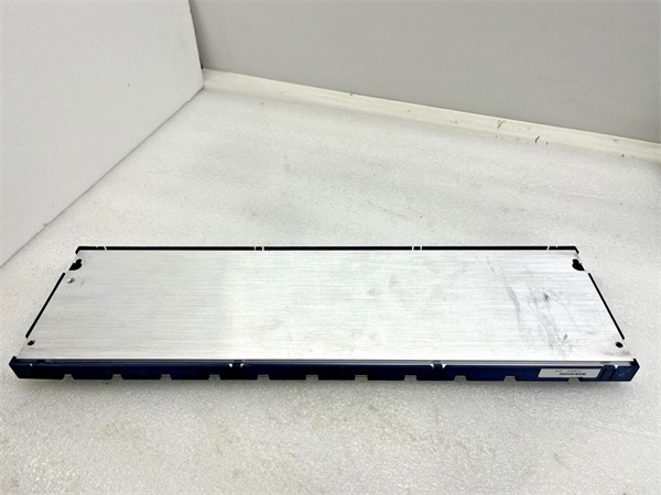
I’ve used these when control cabinets were too crowded for additional I/O. The GE IC694CHS398 is a 5-slot serial expansion backplane that extends your RX3i system’s reach—up to 50 feet from the main rack. That’s practical when you need I/O near machinery but want the controller in a cleaner, temperature-controlled environment.What differentiates this unit from larger backplanes is its compact 5-slot design. You get 170mA at 5VDC internal power consumption, which is actually more efficient per slot than some 10-slot versions. The 50-foot cable limit is the same across the series, but honestly, I rarely push beyond 30 feet—signal integrity degrades noticeably after that distance.
Key Technical Specifications
| Parameter | Value |
|---|---|
| Number of Slots | 5 |
| Backplane Type | High-speed serial only |
| Maximum Expansion Distance | 50 feet (15 meters) |
| Dimensions (H×W×D) | 5.12 × 10.43 × 5.59 inches |
| Weight | Approximately 2.2 pounds |
| Internal Power Consumption | 170 mA @ 5 VDC |
| Required Power Supply | IC694PWR321, IC694PWR330, or IC694PWR331 |
| Operating Temperature | -20°C to +60°C |
| Storage Temperature | -40°C to +85°C |
| Protection Rating | IP20 (standard configuration) |
| Expansion Cable Connector | 25-pin D-shell female |
| Hot Insertion/Removal | Not supported |
| Compatible Backplanes | 12-slot or 16-slot universal backplanes |
GE IC694CHS392
Quality Control Process (SOP Transparency)
Testing 5-slot backplanes requires verifying both mechanical integrity and electrical continuity.
- Incoming Verification: Serial validation against Emerson’s database, visual inspection of all 5 slot connectors and the 25-pin D-shell expansion connector. We check for bent pins—common in shipping—and verify the DIP switch operates smoothly.
- Slot Continuity Test: Using a Fluke 87V multimeter, we verify continuity between each slot’s backplane connections. All 5 slots are tested with a dummy module to ensure proper mechanical fit and electrical contact.
- Power Distribution Test: We install an IC694PWR321 power supply in the leftmost slot and measure voltage at each slot location. Must maintain 5VDC ±5% under 170mA load. The expansion connector’s serial communication signals are verified with an oscilloscope.
- Mechanical Integrity Test: The unit undergoes vibration testing at 5-500Hz for 20 minutes to ensure no loose components. We check mounting hole alignment and verify the plastic guides aren’t cracked or deformed.
- Final QC & Packaging: QC inspector signs off, DIP switches set to default position (address 0), backplate sealed in anti-static wrap with foam corner protection. QC label shows “All 5 slots verified, power distribution within spec.”
GE IC694CHS392
Replacement Pitfall Guide (Field Engineer’s Warnings)
Compact backplanes have their own set of installation quirks—miss one and your expansion won’t work.
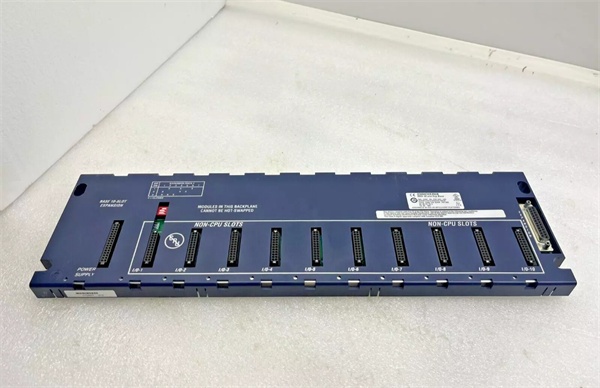
- ❗ Leftmost Slot is Power Supply Only: The first slot (far left) must contain a power supply module—IC694PWR321, IC694PWR330, or IC694PWR331. I’ve seen technicians try to install I/O modules there—won’t work. The backplane needs that power supply to distribute 5VDC to the other slots.
- ❗ DIP Switch Address Must Be Set Before Power-Up: Each GE IC694CHS398 needs a unique address via its DIP switch (0-7). Set this before applying power—the CPU won’t recognize address changes made while the system is running. I’ve wasted hours troubleshooting communication only to find the DIP switch was at the wrong position.
- ❗ 50-Foot Limit is Absolute: The 50-foot maximum includes all daisy-chained cables. If you connect multiple backplanes with IC693CBL302 cables, the total cable length from CPU to the farthest backplane cannot exceed 50 feet. Exceed this and you’ll get intermittent communication failures.
- ❗ No Hot-Swapping—Period: You cannot insert or remove modules while power is applied. The backplane doesn’t support hot insertion—attempting it can damage the module, corrupt communication, or even damage the CPU. Always power down completely before making changes.
- ❗ Ground Loops Kill Serial Communication: The high-speed serial interface is sensitive to ground potential differences. Ensure proper single-point grounding between the CPU rack and all expansion backplanes. A missing ground wire can cause data corruption that’s nearly impossible to diagnose without an oscilloscope.
Keep these five points in mind and you’ll eliminate roughly 90% of rework.