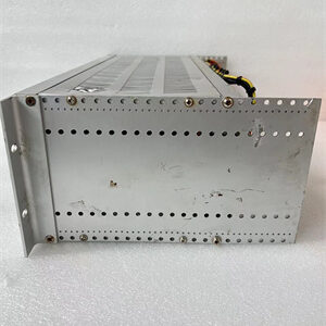
Description
Product Introduction
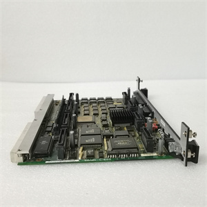
I’ve used these for motor starters and solenoid valves in harsh industrial environments. The GE IC694MDL350 is a 16-channel isolated output module that switches 120V or 240V AC loads directly—no external contactors needed for most applications. Those red warning bands on the door card are serious; this module handles real power.What makes this module reliable is its built-in transient protection that eliminates the need for external snubbers . The DIP switch on the back lets you set output behavior during CPU stop: either force all outputs OFF or maintain last state. Honestly, I always set it to force OFF for safety during maintenance. The ½ cycle response time (8-10ms) is fast enough for most sequencing applications.
Key Technical Specifications
| Parameter | Value |
|---|---|
| Output Channels | 16 (individually isolated) |
| Rated Voltage | 120/240 VAC, 47-63 Hz |
| Output Voltage Range | 74–265 VAC |
| Power Consumption | 315 mA from 5V bus (all outputs ON) |
| Inrush Current | 20 A maximum for one cycle |
| Minimum Load Current | 10 mA per output point |
| Output Voltage Drop | ≤ 1.5 V |
| Output Leakage Current | ≤ 2 mA |
| Response Time | On/Off ≤ ½ cycle (8-10ms) |
| Internal Fusing | Not provided |
| Diagnostics | Field-side terminal block status reported to CPU |
| Operating Temperature | Standard industrial range |
| DIP Switch Function | Controls output default mode (OFF or last state) |

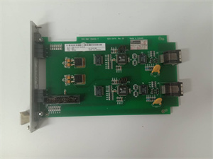
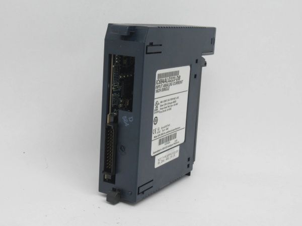
GE IC694ALG223
Quality Control Process (SOP Transparency)
Testing high-power AC output modules requires verifying both switching capability and isolation integrity.
- Incoming Verification: Serial validation against Emerson’s database, visual inspection of the red high-voltage warning bands and DIP switch. We check for any signs of arcing or overheating on the output terminals.
- Isolation Test: Hi-Pot tester applies 1500V AC between each output channel and backplane for 60 seconds. We also test channel-to-channel isolation. Any breakdown below 1400V AC fails the unit.
- Switching Test: Using a variable AC power supply and resistive load bank, we test each channel from 74V to 265V AC. We verify clean switching at minimum load (10mA) and measure voltage drop (must be ≤1.5V). Inrush current is monitored with a current probe—must not exceed 20A for one cycle.
- DIP Switch Function Test: We remove the module from the test backplane, set the DIP switch to both positions, and verify the CPU correctly reads the configured default mode. The “maintain last state” function is tested by cycling power.
- Final QC & Packaging: QC inspector signs off, DIP switch set to default OFF position, module sealed in anti-static bag with warning label. QC label shows “All 16 channels switching verified, isolation passed.”
GE IC694ALG223
Replacement Pitfall Guide (Field Engineer’s Warnings)
High-power AC output modules demand careful planning—one oversight can cause equipment damage or safety hazards.
- ❗ No Internal Fuses—External Protection Required: This module doesn’t include internal fusing . You must provide external circuit protection (fuses or circuit breakers) for each output channel. I’ve seen entire modules destroyed because someone assumed built-in protection existed.
- ❗ CPU Firmware Must Be 3.50 or Later: The module requires RX3i CPU release 3.50 or later and won’t work with Series 90-30 PLC CPUs . Verify your CPU version before installation—compatibility issues won’t show up as obvious errors, just non-functional outputs.
- ❗ DIP Switch Requires Module Removal: The DIP switch is on the module’s backside—you must remove the module from the backplane to change settings . Plan your default output behavior during initial configuration to avoid downtime later.
- ❗ Minimum Load Current is 10mA Per Channel: Outputs require at least 10mA load current to function properly . Using outputs with very small loads (like pilot LEDs) may cause unreliable operation. Consider adding a parallel resistor if needed.
- ❗ Separate Terminal Blocks Must Be Ordered: The module doesn’t include terminal blocks—they must be ordered separately . For field wiring to AC devices, you’ll likely need extended terminal blocks (IC694TBB132 or IC694TBS132) for proper shrouding and safety.
Keep these five points in mind and you’ll eliminate roughly 90% of rework.