Description
Product Introduction
I’ve installed the GE IC694MDL632 in noisy industrial settings for motor contactors and limit switches. This 16-channel isolated input module reads 120V AC signals directly, with red warning bands signaling high voltage.Unlike basic AC inputs, this unit offers software-programmable filtering (20-2440ms in 20ms steps) and 30ms on-response time—faster than older 45ms models. Its 16 isolated channels support mixed-phase AC sources, a practical edge in complex setups (—though your mileage may vary depending on ambient noise).
Key Technical Specifications
| Parameter | Value |
|---|---|
| Input Channels | 16 (individually isolated) |
| Rated Voltage | 120 VAC, 47-63 Hz |
| Input Voltage Range | 0–132 VAC |
| On-State Voltage | >70 VAC |
| Off-State Voltage | <20 VAC |
| Input Current | 7.0 mA typical (rated), ≥5 mA on, ≤2.5 mA off |
| Isolation Rating | 1500 VAC (1 min, channel-to-backplane/group) |
| Response Time | 30 ms on, 45–55 ms off |
| Filter Time Range | 20–2440 ms (20 ms increments) |
| Power Consumption | 200 mA @ 5 VDC (all inputs on) |
| Operating Temperature | -20°C to +55°C |
| Certifications | UL 508, CSA C22.2 No.142, Class I Div.2 |
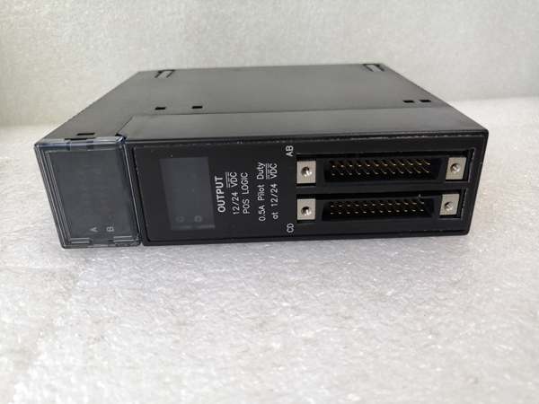
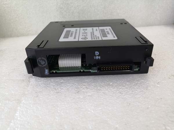
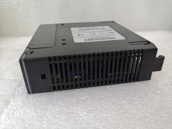
GE IC693MDL753
Quality Control Process (SOP Transparency)
We test this module like it’s headed for a motor control center—no shortcuts.
- Incoming Verification: Serial number validated against Emerson’s database. Visual inspection checks red high-voltage warning bands, terminal block lock indicator (green TB LED when locked), and isolation barrier for damage. Accessories audit confirms no missing parts.
- Live Functional Test: Installed in an ABB AC800M test rack with RX3i CPU. A Fluke 725 calibrator injects 0-140 VAC signals into each channel. We verify on/off states at 74-132 VAC (on) and <20 VAC (off), logging response times with a scope. Continuous load test runs 24 hrs with temp logging.
- Electrical Parameter Test: 500 V Megger measures insulation resistance (>10 MΩ). Ground continuity verified from terminal block to chassis.
- Firmware Verification: Firmware version read via Proficy Machine Edition, photographed with DIP switch settings (default: filter enabled).
- Final QC & Packaging: QC inspector signs off. Terminal screws torqued to spec. Module sealed in anti-static bag with desiccant, bubble-wrapped, and boxed. QC Passed label notes test date, isolation result, and all 16 channels verified.
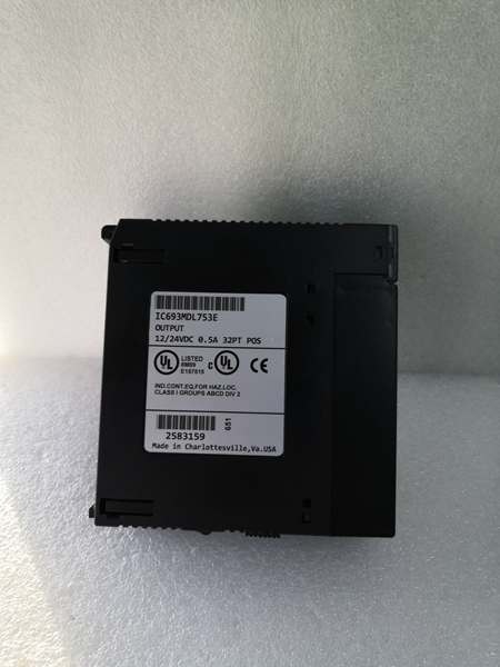
GE IC693MDL753
Replacement Pitfall Guide (Field Engineer’s Warnings)
The GE IC694MDL632 has quirks—learn them to avoid downtime.
- ❗ Firmware Rev Mismatch: New module firmware too new/old → comms timeouts. Record current firmware before swapping. Case: An engineer swapped a module on a running line — the PLC threw “Communication Timeout”. Root cause: firmware jumped from V2.8 to V3.1.
- ❗ DIP Switch / Jumper Misconfiguration: Factory defaults rarely match field needs. Photograph the old module. Bus termination resistors (120 Ω) belong at physical ends only. “This is the most common rookie mistake. Photograph it.”
- ❗ Terminal / Cable Incompatibility: Pin definitions change between revisions. Pull the wiring diagram. Siemens S7-300 modules are a known example: similar part numbers, different pin assignments.
- ❗ Power Budget Shortfall: Replacement modules may draw more current. Calculate total rack power and maintain 20% headroom. Example: Add 10 AI modules and total rack load can hit 60 W — a 24 V / 2.5 A supply won’t cut it.
- ❗ ESD Damage: Static discharge kills modules silently. Wear a wrist strap. Work on an anti-static mat. A module powered up, smoked, and was dead on arrival — $2,000 gone because an engineer skipped the wrist strap.
Keep these five points in mind and you’ll eliminate roughly 90% of rework.