Description
Product Introduction
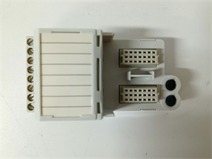
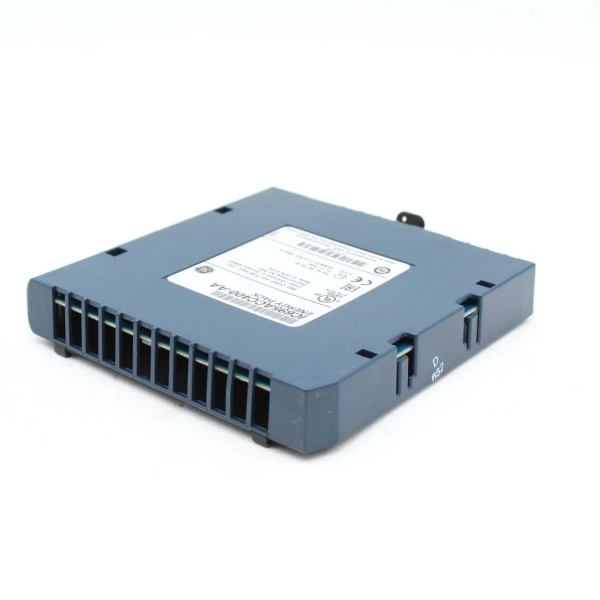
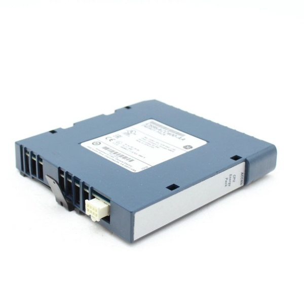
I’ve installed hundreds of these terminal bases—they’re the workhorse interface between field wiring and your RX3i I/O cards. The GE IC694TBB032 is a 36-pin terminal base block designed for PACSystem RX3i high-density discrete I/O modules, though it also works with some 90-30 series modules .This unit uses screw-type connections rated for 10 A per terminal and accepts 14-26 AWG solid or stranded copper wire. The two-part design—module cover and terminal block—assembles quickly and connects directly to the I/O module .
Key Technical Specifications
| Parameter | Value |
|---|---|
| Terminal Count | 36 screw-type terminals |
| Wire Range | 14-26 AWG solid/stranded copper |
| Rated Voltage | 300 VAC/DC |
| Rated Current | 10 A per terminal |
| Operating Temperature | -25 to +70°C |
| Storage Temperature | -40 to +85°C |
| Dimensions | 120 × 60 × 40 mm |
| Weight | 0.14 kg |
| Mounting | DIN rail or panel |
| Material | Flame-retardant plastic housing |
| Stripping Length | 7.87 mm (0.310 in) |
| Torque | 7 lb-in |
GE IC695ACC400
Quality Control Process (SOP Transparency)
Terminal blocks fail when you least expect it—usually during a rainy night shift. Here’s how we verify each IC694TBB032.
- Incoming Verification: Cross-reference part number against Emerson’s compatibility matrix. Check for GE Intelligent Platforms or Emerson Automation branding. Inspect screw terminals for proper plating and spring tension—corroded terminals mean moisture ingress.
- Live Functional Test: Mount on standard DIN rail with test I/O module (IC694MDL740). Torque all 36 screws to 7 lb-in using Wiha torque screwdriver. Connect 14 AWG and 26 AWG wires, verify secure connections without strand breakage.
- Electrical Parameter Test: Measure insulation resistance at 500 V between adjacent terminals (>100 MΩ). Verify continuity through each terminal with Fluke 87V. Check dielectric strength at 1500 VAC for 60 seconds.
- Firmware Verification: No firmware, but document manufacturing date code and lot number. Photograph UL/CE markings and terminal numbering.
- Final QC & Packaging: Inspector signs off after confirming all screws turn freely. Seal in anti-static bag with desiccant. Bubble wrap and carton with QC label showing torque verification date.
GE IC695ACC400
Replacement Pitfall Guide (Field Engineer’s Warnings)
The IC694TBB032 looks simple but has specific failure modes that only appear under vibration. Keep these five points in mind and you’ll eliminate roughly 90% of rework.
- ❗ Wire Size Mismatch: Rated for 14-26 AWG only—smaller wires vibrate loose. Case: An engineer used 28 AWG sensor wiring—the screws couldn’t clamp properly, causing intermittent faults during machine startup.
- ❗ Torque Overkill: 7 lb-in maximum—overtightening strips the brass inserts. “I’ve seen more terminals damaged by overzealous electricians than by actual electrical faults. Use a torque-limiting driver.”
- ❗ Stranded Wire Preparation: Tin the ends or use ferrules on stranded wire. Bare strands splay under the screw, reducing contact area and increasing resistance over time.
- ❗ Module Compatibility: Works with high-density discrete I/O and some 90-30 modules—check the manual. Not all RX3i analog modules use this base—verify before ordering.
- ❗ Environmental Rating: IP20 only—no dust or water protection. Install in sealed enclosures for washdown areas. I’ve seen corrosion on terminals in food plants within six months of exposure.