Description
Hard-Numbers: Technical Specifications
- Channel Configuration: 8 single-ended or 4 differential input channels .
- Voltage Input Ranges: ±10 VDC, 0-10 VDC, ±5 VDC, 0-5 VDC, 1-5 VDC .
- Current Input Ranges: 0-20 mA, 4-20 mA, ±20 mA .
- ADC Resolution: 24-bit sigma-delta converter .
- Data Format: Integer or 32-bit IEEE floating-point .
- Configurable Input Filter: 6 selectable frequencies (8 Hz, 12 Hz, 16 Hz, 40 Hz, 200 Hz, 500 Hz) per channel .
- Isolation Rating: Non-isolated – all channels share a common reference .
- Operating Temperature: 0°C to +60°C (standard industrial range).
- Backplane Current: 5V @ 600mA max; 3.3V @ 450mA max .
- Required Firmware: RX3i CPU firmware 3.0 or later; Proficy Machine Edition 5.0 SP3 or later .
- Required Terminal Block: IC694TBB032 (Box), IC694TBB132 (Extended Box), IC694TBS032 (Spring), or IC694TBS132 (Extended Spring) .
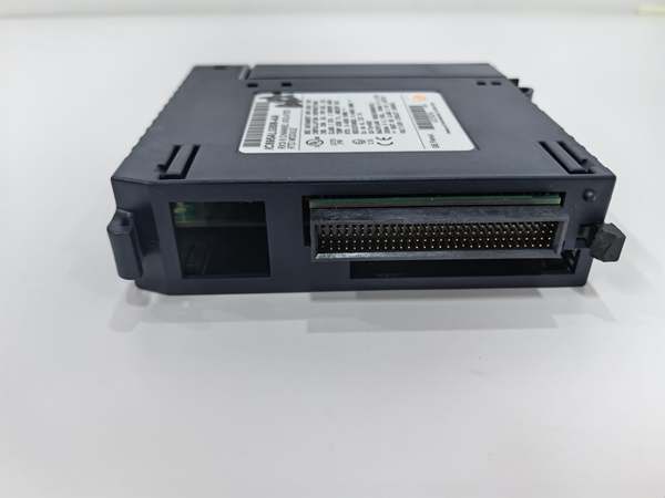
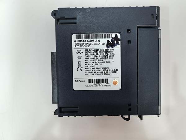
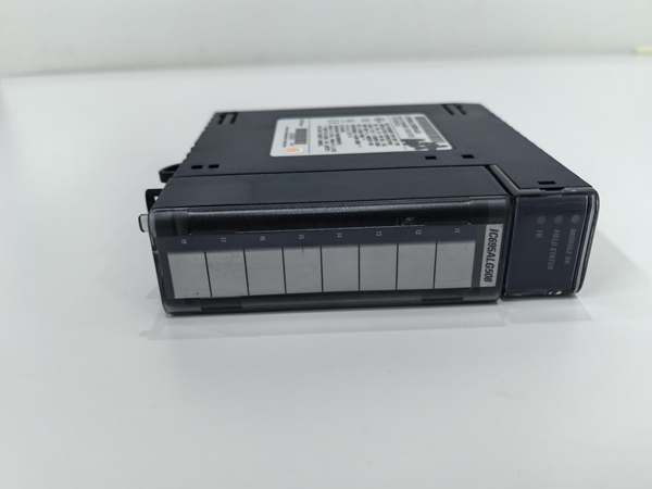
GE IC695ALG508
The Real-World Problem It Solves
Isolated input cards cost more and consume more real estate. For a control panel where all your 4-20mA transmitters and 0-10V potentiometers are powered from the same 24VDC supply and share a common ground, paying for channel-to-channel isolation is wasted money and panel space.Where you’ll typically find it:
- Machine Control Panels: Reading multiple motor speed references (0-10V) and analog feedback signals from drives within the same cabinet.
- Batching Systems: Monitoring weigh scale load cells (mV/V) and valve position feedback (4-20mA) where all sensors are locally powered.
- Test Stands & Lab Rigs: Where signal sources are bench power supplies and data acquisition is from a controlled, single-ground environment.
It’s the workhorse for cost-effective analog acquisition when your signal sources already share a clean, common ground.
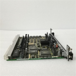
Hardware Architecture & Under-the-Hood Logic
This is a non-isolated module, meaning all eight channels reference the same common ground point on the backplane. The front-end uses programmable gain amplifiers and multiplexers to route each channel’s signal to a high-resolution 24-bit sigma-delta ADC . The configuration for single-ended vs. differential is done in software, which internally switches the multiplexer paths.
- Input Multiplexing & Conditioning: Based on the channel’s software configuration (voltage/current, range), internal solid-state switches connect the input to the appropriate scaling network. A current input is routed through a precision shunt resistor to convert mA to a measurable voltage .
- Differential vs. Single-Ended Routing: When configured for differential input, the module uses two physical terminals per channel to measure the voltage difference between them, rejecting common-mode noise. In single-ended mode, each channel measures the voltage between its terminal and the common ground .
- Sigma-Delta Conversion & Filtering: The conditioned signal is digitized by the 24-bit ADC. A user-selectable digital filter (8Hz to 500Hz) is then applied to smooth the reading and reject out-of-band noise .
- Diagnostics & Data Handling: The module performs continuous diagnostics: open-circuit detection for 4-20mA loops (by monitoring for a near-zero mA reading), over-range/under-range checks, and module health monitoring. Scaled data and status bits are sent to the CPU .
GE IC695ALG508
Field Service Pitfalls: What Rookies Get Wrong
Creating Ground Loops with Single-Ended WiringThe biggest trap with non-isolated modules. You wire a 4-20mA transmitter located 100 feet away, grounding its negative wire at the sensor and again at the module’s common terminal. This creates a ground loop—stray currents flow through the signal wire, adding offset or noise to your reading.
- Field Rule: Establish a single-point ground for the entire analog loop. Typically, ground the shield and the signal common at the module end only. Leave the field device floating if possible. Use a differential input configuration for long wire runs in noisy environments.
Using Differential Mode UnnecessarilyA rookie sees “differential” and thinks it’s always better, configuring all channels as differential. This cuts your available channels from 8 to 4. For signals sourced within the same cabinet (like a local potentiometer), single-ended mode is perfectly adequate and doubles your point count.
- Quick Fix: Reserve differential mode for long wire runs (>50 ft) or electrically noisy environments. Use single-ended mode for short, local signals to maximize your I/O density. Document the wiring scheme in the panel drawing.
Ignoring the Common-Mode Voltage LimitBecause the module is non-isolated, all input voltages are referenced to the backplane ground. If you connect a signal whose negative lead is at a different ground potential (e.g., a device powered from a separate, noisy supply), you can exceed the common-mode voltage range, saturate the input amplifier, and get garbage data.
- Field Rule: Verify all field devices share the same power supply ground or are within the module’s specified common-mode voltage range. If in doubt, measure the voltage between the field device’s negative terminal and the module’s common terminal with a multimeter before connecting. A reading more than a few volts indicates a ground potential difference problem.
Commercial Availability & Pricing NotePlease note: The listed price is for reference only and is not binding. Final pricing and terms are subject to negotiation based on current market conditions and availability.