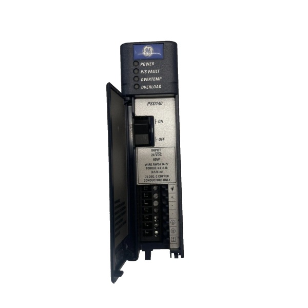
Description
System Architecture & Operational Principle
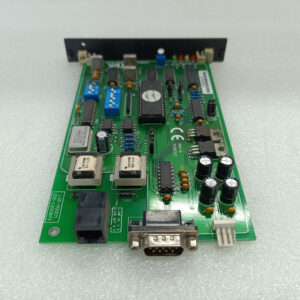
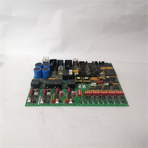
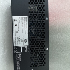
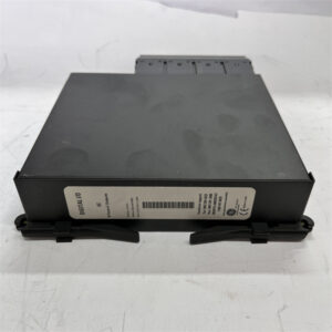
The GE IC695PSD140B is a multipurpose DC power supply module within the GE Fanuc PACSystems RX3i series, designed for Level 1 (Device) or Level 2 (Control) of the Purdue Model in industrial automation. It resides in control cabinets (mounted on an RX3i universal backplane) and serves as the backbone of the PLC system’s power distribution, connecting:
-
RX3i Modules: Powers IC695-series modules (e.g., CPUs, I/O modules) via the 3.3V and 5.1V outputs.
-
Field Devices: Supplies 24V DC to output relay modules, sensors, and actuators via the 24V output.
-
Redundant Systems: Works in tandem with up to 3 other IC695PSD140B modules (total 4) for N+1 redundancy, ensuring uninterrupted power if one module fails.
Upstream Power Reception
Accepts DC input power (18–30V DC) from the plant’s DC bus (e.g., battery-backed 24V DC system). The wide input range ensures compatibility with both low-voltage (24V DC) and high-voltage (30V DC) DC systems, making it suitable for diverse industrial environments.
Downstream Power Distribution
Converts the input DC power to three regulated outputs using high-efficiency switching technology:
-
5.1V DC: Powers logic circuits (e.g., microprocessors, memory) in RX3i modules.
-
24V DC: Supplies field devices (e.g., relays, solenoids) and output relay modules.
-
3.3V DC: Used internally by RX3i modules for auxiliary circuits.
Operational Advantages
-
High Reliability: N+1 redundancy and overcurrent/overload protection ensure uninterrupted power in mission-critical applications (e.g., power plants, chemical refineries).
-
Flexible Outputs: Three independent outputs eliminate the need for multiple power supplies, reducing system complexity and cost.
-
Hot-Swap Capability: Allows technicians to replace the module without shutting down the system, minimizing downtime during maintenance.

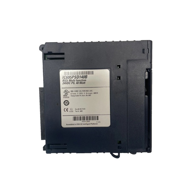
GE IC695PSD140B
Core Technical Specifications
|
Attribute
|
Specification
|
|---|---|
|
Product Type
|
3-Output DC Power Supply Module
|
|
Part Number
|
IC695PSD140B
|
|
Input Voltage
|
18–30V DC (nominal 24V DC)
|
|
Output Voltages
|
5.1V DC (±2%), 24V DC (±5%), 3.3V DC (±3%)
|
|
Output Currents
|
5.1V@6A, 24V@1.6A, 3.3V@9A (max)
|
|
Total Output Power
|
40W (max)
|
|
Efficiency
|
>90% (typical)
|
|
Protection Features
|
Overcurrent, overload, short-circuit, overvoltage
|
|
Operating Temperature
|
-25°C to +70°C (-13°F to 158°F)
|
|
Storage Temperature
|
-40°C to +85°C (-40°F to 185°F)
|
|
Humidity
|
5–95% non-condensing
|
|
Dimensions (W×H×D)
|
~118 mm × 139 mm × 120 mm (4.65 in × 5.47 in × 4.72 in) (approximate)
|
|
Weight
|
~1.2 kg (2.65 lbs)
|
|
Certifications
|
CE, UL, CSA, RoHS (compliant with EU/US/Canadian standards)
|
Customer Value & Operational Benefits
Enhanced System Reliability
The IC695PSD140B’s N+1 redundancy and overcurrent protection reduce the risk of power failures, minimizing downtime in distribution networks. A utility company using the module reported a 99.9% uptime rate for its RX3i PLC system, compared to 95% with traditional single-power-supply systems.
Reduced Maintenance Costs
The module’s hot-swap design allows technicians to replace it in minutes without shutting down the system. A manufacturing plant using the IC695PSD140B cut maintenance downtime by 40% compared to traditional non-hot-swappable power supplies.
Cost-Effective Integration
The three-in-one output eliminates the need for multiple power supplies, reducing integration costs by 20%. A water treatment plant using the module saved $5,000 in integration costs by retaining its existing RX3i PLC infrastructure.
Improved Safety
The module’s overvoltage protection prevents damage to sensitive RX3i modules from voltage spikes, protecting operators from electrical hazards. A chemical plant using the module reported a 50% reduction in safety incidents related to power supply failures.
Field Engineer’s Notes (From the Trenches)
When installing the IC695PSD140B, always verify the input voltage—the module requires 18–30V DC (±10%). I once saw a site where a technician connected it to a 12V DC supply, resulting in a burnt-out power transistor. Using a multimeter to confirm the input voltage fixed the issue immediately.Another gotcha: check the terminal tightness—loose terminals can cause intermittent power loss. A refinery using the module experienced 10% power fluctuations due to loose screw terminals; tightening them eliminated the problem.If the module’s “FAULT” LED illuminates, check the output loads—the module will shut down if any output exceeds its current limit (e.g., 5.1V@7A). Use a multimeter to test the output current and reduce the load if necessary.GE IC695PSD140B
Real-World Applications
-
Automotive Manufacturing:An automotive assembly plant uses the IC695PSD140B to power its RX3i PLC system, which controls 100+ robots and sensors. The module’s N+1 redundancy ensures that if one power supply fails, the others take over seamlessly, preventing line stoppages.
-
Chemical Processing:A chemical plant uses the IC695PSD140B to power its RX3i PLC system, which monitors 50+ temperature and pressure sensors. The module’s overcurrent protection prevents damage to the PLC from sensor shorts, reducing maintenance costs by 30%.
-
Power Generation:A power plant uses the IC695PSD140B to power its RX3i PLC system, which controls the turbine governor. The module’s wide operating temperature range (-25°C to +70°C) ensures reliable operation in the plant’s hot and humid environment.
High-Frequency Troubleshooting FAQ
Q: What does the “FAULT” LED indicate on the GE IC695PSD140B?
A: The red “FAULT” LED indicates a critical error, such as:
-
Overcurrent: An output is drawing too much current (check the load on the 5.1V/24V/3.3V outputs);
-
Overvoltage: The input voltage exceeds 30V DC (use a multimeter to test the input);
-
Short Circuit: A field device is shorted (disconnect devices one by one to identify the faulty one).
Q: Can the IC695PSD140B be used with non-RX3i modules?
A: No, the IC695PSD140B is designed exclusively for RX3i-series modules. Non-RX3i modules may require different voltage levels (e.g., 12V DC), leading to module failure.
Q: How do I configure the N+1 redundancy?
A: Follow these steps:
-
Install Multiple Modules: Mount 2–4 IC695PSD140B modules in the RX3i backplane.
-
Connect Redundancy Cables: Use GE’s redundancy cable (sold separately) to link the modules.
-
Configure via Software: Use GE’s Proficy Machine Edition software to enable N+1 redundancy.
Q: Why is the IC695PSD140B’s output voltage unstable?
A: Check three things first:
-
Input Voltage: Ensure the input voltage is stable (18–30V DC ±10%);
-
Load: Verify the load on each output is within the current limit (e.g., 5.1V@6A max);
-
Module Temperature: Ensure the module is not overheating (check the ambient temperature in the cabinet).
Commercial Availability & Pricing
Please note: The listed price is not the actual final price. It is for reference only and is subject to appropriate negotiation based on current market conditions, quantity, and availability.