Description
System Architecture & Operational Principle
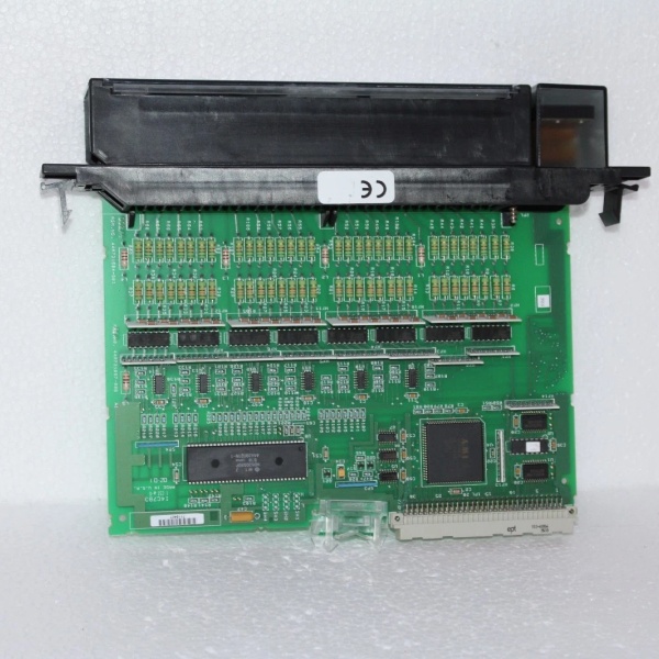
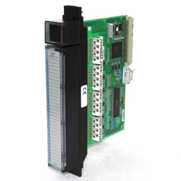
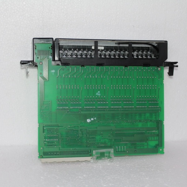
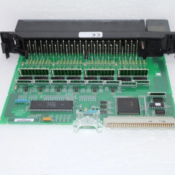
The GE IC697MDL654 is a 32-point 48VDC discrete input module within the GE Fanuc Series 90-70 PLC family, designed for Level 1 (Device) or Level 2 (Control) of the Purdue Model in industrial automation. It resides in control cabinets (mounted on a Series 90-70 CPU baseplate) and serves as the bridge between field devices (e.g., proximity sensors, pushbuttons, level switches) and higher-level controllers (e.g., GE 90-70 PLCs).
Upstream Communication
Receives digital signals (48VDC) from field devices via screw terminals or pre-wired cables. The module supports positive/negative logic (selectable via software), allowing it to adapt to diverse field device configurations.
Downstream Communication
Transmits processed data to the controller via the Series 90-70 backplane. The module uses opto-couplers for backplane isolation, preventing ground loops and protecting sensitive electronics from voltage spikes.
Operational Advantages
-
High Density: 32 input points in a compact form factor save space in control cabinets, ideal for applications with limited real estate (e.g., manufacturing lines, process control skids).
-
Flexible Logic: Supports both positive and negative logic, eliminating the need for additional signal conditioning for different field devices.
-
Rugged Design: Wide operating temperature range (-40°C to +85°C) and IP20 enclosure rating make it suitable for harsh industrial environments (e.g., power plants, chemical refineries).

GE IC697MDL654
Core Technical Specifications
|
Attribute
|
Specification
|
|---|---|
|
Product Type
|
32-Point 48VDC Discrete Input Module
|
|
Part Number
|
IC697MDL654
|
|
Number of Inputs
|
32 (divided into 4 groups of 8)
|
|
Input Voltage
|
48VDC nominal (–3 to +56VDC range)
|
|
Input Current
|
4.7 mA per channel (typical at rated voltage)
|
|
Logic Type
|
Positive/Negative (software-selectable)
|
|
Isolation
|
1500V RMS (field-to-logic); 500V RMS (group-to-group)
|
|
Response Time
|
1–10 ms (selectable per module via filter settings)
|
|
Power Consumption
|
0.30 A from 5VDC backplane
|
|
Operating Temperature
|
0°C to +60°C (32°F to 140°F)
|
|
Storage Temperature
|
-40°C to +85°C (-40°F to 185°F)
|
|
Humidity
|
5–95% non-condensing
|
|
Dimensions (W×H×D)
|
~200 mm × 40 mm × 150 mm (7.9 in × 1.6 in × 5.9 in) (approximate)
|
|
Weight
|
~0.75 kg (1.65 lbs)
|
|
Certifications
|
CE, UL, CSA (compliant with EU/US/Canadian standards)
|
Customer Value & Operational Benefits
Enhanced System Flexibility
The IC697MDL654’s 32 input points and flexible logic allow it to integrate multiple field devices into a single module, reducing the number of components needed in the control cabinet. This flexibility is critical for applications like assembly lines or process control, where multiple sensors need to be monitored simultaneously.
Reduced Maintenance Costs
The module’s hot-swap design (when used with compatible baseplates) allows technicians to replace it in minutes without shutting down the system. A manufacturing plant using the IC697MDL654 cut maintenance downtime by 40% compared to traditional non-hot-swappable input modules.
Cost-Effective Integration
Compatible with GE’s Series 90-70 PLCs and third-party controllers (e.g., Siemens S7-1200), the IC697MDL654 eliminates the need for custom interfaces. A water treatment plant using the module saved $10,000 in integration costs by retaining its existing PLC infrastructure.
Field Engineer’s Notes (From the Trenches)
When installing the IC697MDL654, always use pre-wired cables (e.g., IC697CBL327) for reliable connections—loose wires can cause intermittent signal loss. I once saw a site where a technician used unshielded cables, resulting in a 15% error rate in sensor data. Switching to pre-wired cables eliminated the problem immediately.Another gotcha: verify the logic type—the module defaults to positive logic, but if you’re using negative logic devices, you must adjust the settings via the controller’s programming software (e.g., Logicmaster 90-70). I’ve fixed countless “no signal” errors by forgetting to switch the logic type.If the module’s “FAULT” LED illuminates, check the input voltage—the module requires a stable 48VDC supply. I’ve seen cases where a faulty power supply (outputting 36VDC) caused the module to enter a fault state. Use a multimeter to test the input voltage before replacing the module.GE IC697MDL654
Real-World Applications
-
Manufacturing Lines:An automotive manufacturing plant uses the IC697MDL654 to monitor 32 proximity sensors on an assembly line. The module’s fast response time (<10 ms) allows the PLC to adjust the line speed based on sensor inputs, reducing product defects by 20%.
-
Chemical Processing:A chemical plant uses the IC697MDL654 to monitor 16 level switches and 16 pressure sensors in a reactor. The module’s 1500V isolation prevents ground loops from damaging the PLC, ensuring reliable operation of the chemical process.
-
Power Generation:A power plant uses the IC697MDL654 to monitor 32 temperature sensors in a turbine. The module’s wide operating temperature range (-40°C to +85°C) ensures reliable operation in the plant’s hot and humid environment.
High-Frequency Troubleshooting FAQ
Q: What does the “FAULT” LED indicate on the GE IC697MDL654?
A: The red “FAULT” LED indicates a critical error, such as:
-
Power Supply Failure: The input voltage is outside the –3 to +56VDC range (check with a multimeter);
-
Overload: A channel is drawing too much current (check the field device’s output);
-
Module Fault: The internal opto-coupler or circuitry is faulty (replace the module).
Q: Can the IC697MDL654 be used with non-GE controllers?
A: Yes, the module’s 48VDC input is compatible with most controllers (e.g., Siemens S7-1200, Allen-Bradley CompactLogix). However, you may need to adjust the wiring (e.g., terminal blocks) to match the controller’s requirements.
Q: How do I configure the logic type (positive/negative) on the IC697MDL654?
A: Use GE’s Logicmaster 90-70 software to configure the logic type:
-
Open Logicmaster 90-70: Launch the software and connect to the PLC.
-
Select the IC697MDL654: Navigate to the “I/O Configuration” tab and select the module.
-
Set Logic Type: Choose “Positive” or “Negative” for each channel.
-
Save Configuration: Click “Save” to apply the changes to the module’s memory.
Q: Why is the IC697MDL654’s signal unstable?
A: Check three things first:
-
Power Supply: Ensure the 48VDC power supply is stable (use a multimeter to test);
-
Cables: Verify the pre-wired cables are not damaged (check for cuts or breaks);
-
Field Device: Ensure the field device (e.g., sensor) is not faulty (test with a multimeter).
Commercial Availability & Pricing
Please note: The listed price is not the actual final price. It is for reference only and is subject to appropriate negotiation based on current market conditions, quantity, and availability.