Description
System Architecture & Operational Principle
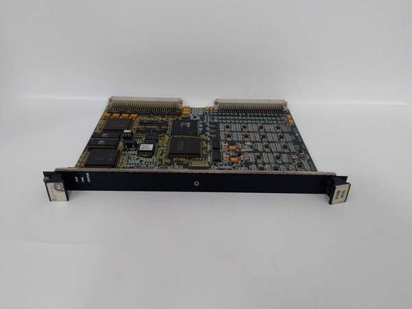
The GE IS200VVIBH1C is a 14-channel vibration monitoring module within the GE Mark VI Speedtronic Turbine Control System, designed for Level 2 (Control) or Level 3 (Operations) of the Purdue Model in industrial automation. It resides in the VME rack (mounted via front-panel screws) and serves as the bridge between vibration sensors (e.g., TVIB/DVIB terminal boards) and the Mark VI controller, connecting:
-
Vibration Sensors: Receives analog signals from 14 vibration probes (e.g., accelerometers, proximity sensors) via TVIB/DVIB terminal boards. These sensors measure vibration in turbine components (e.g., bearings, shafts, casings).
-
Mark VI Controller: Transmits digitized vibration data to the controller via the VME backplane. The controller uses this data for:
-
Real-Time Monitoring: Displaying vibration trends on the operator interface (HMI).
-
Fault Detection: Identifying abnormal vibration patterns (e.g., imbalance, misalignment) and triggering alarms.
-
Predictive Maintenance: Providing data for maintenance scheduling (e.g., bearing replacement before failure).
-
-
Redundant Systems: In TMR (Triple Modular Redundancy) configurations, works with two other IS200VVIBH1C modules to provide redundant vibration data, ensuring reliability in mission-critical applications.
Upstream Signal Reception
Receives analog vibration signals from TVIB/DVIB terminal boards. The module uses low-noise amplifiers to condition the signals (reduce noise) before converting them to digital data.
Downstream Communication
Converts analog signals to 16-bit digital data using a high-resolution A/D converter. The digital data is transmitted to the Mark VI controller via the VME backplane for processing.
Operational Advantages
-
High Precision: 16-bit A/D resolution ensures accurate vibration measurement (±0.1% of full scale), critical for detecting minor faults.
-
Redundancy: TMR configuration provides fail-safe operation, with redundant modules taking over if one fails.
-
Flexible Sensor Support: Compatible with multiple vibration sensor types (accelerometers, proximity probes), allowing adaptation to diverse turbine designs.

GE IS200VVIBH1C
Core Technical Specifications
|
Attribute
|
Specification
|
|---|---|
|
Product Type
|
14-Channel Vibration Monitoring Module
|
|
Part Number
|
IS200VVIBH1C (Alias: IS200VVIBH1CAC)
|
|
System Platform
|
GE Mark VI Speedtronic Turbine Control System
|
|
Number of Channels
|
14 (supports up to 14 vibration probes via TVIB/DVIB terminal boards)
|
|
Sensor Compatibility
|
Accelerometers, proximity probes, velocity sensors (via TVIB/DVIB)
|
|
A/D Resolution
|
16-bit
|
|
Input Voltage Range
|
-20V to +20V (analog vibration signals)
|
|
Power Supply
|
24V DC (nominal); 20–30V DC (operational range)
|
|
Communication Interface
|
VME bus (backplane)
|
|
Operating Temperature
|
-40°C to +85°C (-40°F to 185°F)
|
|
Storage Temperature
|
-55°C to +90°C (-67°F to 194°F)
|
|
Humidity
|
5–95% non-condensing
|
|
Dimensions (W×H×D)
|
~105 mm × 45 mm × 25 mm (4.1 in × 1.8 in × 1.0 in) (approximate)
|
|
Weight
|
~0.3 kg (0.66 lbs)
|
|
Certifications
|
CE, UL, RoHS (compliant with EU/US/Canadian standards)
|
Customer Value & Operational Benefits
Enhanced Turbine Reliability
The IS200VVIBH1C’s high-precision vibration monitoring and fault detection capabilities reduce the risk of turbine damage from unbalance, misalignment, or bearing wear. A power plant using the module reported a 30% reduction in unplanned downtime due to early detection of vibration anomalies.
Reduced Maintenance Costs
The module’s predictive maintenance data allows technicians to schedule maintenance proactively, reducing emergency repairs and downtime. A chemical plant using the IS200VVIBH1C cut maintenance costs by 25% compared to traditional reactive maintenance.
Cost-Effective Integration
Compatible with GE Mark VI systems and third-party vibration sensors (e.g., Siemens, ABB), the IS200VVIBH1C eliminates the need for custom signal conditioners. A water treatment plant using the module saved $10,000 in integration costs by retaining its existing Mark VI infrastructure.
Improved Process Visibility
The module’s real-time data transmission to the Mark VI controller enables operators to monitor vibration trends and adjust process parameters proactively. A gas turbine plant using the IS200VVIBH1C improved energy efficiency by 10% by optimizing turbine speed based on vibration data.
Field Engineer’s Notes (From the Trenches)
When installing the IS200VVIBH1C, always use TVIB/DVIB terminal boards to connect vibration sensors—direct wiring to the module can cause signal distortion. I once saw a site where a technician bypassed the terminal board, resulting in a 15% error rate in vibration measurements. Using the terminal board fixed the issue immediately.Another gotcha: verify the sensor type—the module supports accelerometers, proximity probes, and velocity sensors. If you use an unsupported sensor (e.g., a microphone), the module will report incorrect vibration data. Use a multimeter to test the sensor’s output (e.g., 4–20 mA for accelerometers) and confirm it matches the module’s configuration.If the module’s fault LED illuminates, check the vibration sensors—the most common cause is a faulty sensor (e.g., broken wire, contaminated probe). Use the Mark VI controller’s diagnostic tool to identify the faulty sensor and replace it.GE IS200VVIBH1C
Real-World Applications
-
Power Generation:A coal-fired power plant uses the IS200VVIBH1C to monitor the vibration of 14 bearings in a 500 MW steam turbine. The module’s TMR configuration ensures that if one module fails, the other two continue to provide vibration data, preventing turbine shutdown.
-
Gas Turbines:A natural gas power plant uses the IS200VVIBH1C to monitor the vibration of a 150 MW gas turbine’s compressor. The module’s real-time data transmission to the Mark VI controller enables operators to adjust the turbine’s balance weights, reducing vibration by 25% and extending bearing life.
-
Chemical Processing:A chemical plant uses the IS200VVIBH1C to monitor the vibration of a 100 MW turbine-driven compressor. The module’s fault detection feature identifies bearing wear early, allowing technicians to replace the bearing before it fails, preventing downtime.
High-Frequency Troubleshooting FAQ
Q: What does the fault LED on the GE IS200VVIBH1C indicate?
A: The fault LED indicates a critical error, such as:
-
Sensor Fault: A vibration sensor is disconnected or faulty (check the sensor’s resistance with a multimeter);
-
Signal Distortion: The analog signal from the sensor is outside the -20V to +20V range (use an oscilloscope to test the signal);
-
Module Fault: The internal A/D converter or power supply is faulty (replace the module).
Q: Can the IS200VVIBH1C be used with non-GE vibration sensors?
A: Yes, the module is compatible with most third-party vibration sensors (e.g., Siemens, ABB) that support TVIB/DVIB terminal boards. However, you may need to adjust the sensor configuration (via the Mark VI controller’s software) to match the sensor’s output (e.g., 4–20 mA vs. 0–10 V).
Q: How do I configure the vibration thresholds on the IS200VVIBH1C?
A: Use GE’s ToolboxST software to configure the vibration thresholds:
-
Open ToolboxST: Launch the software and connect to the Mark VI controller.
-
Select the IS200VVIBH1C: Navigate to the “I/O Configuration” tab and select the module.
-
Set Thresholds: Enter the vibration thresholds (e.g., 4 mm/s for bearings) for each channel.
-
Save Configuration: Click “Save” to apply the changes to the module’s memory.
Q: Why is the IS200VVIBH1C’s vibration reading unstable?
A: Check three things first:
-
Sensor: Ensure the vibration sensor is clean (no dirt or debris) and properly aligned with the turbine component.
-
Wiring: Verify the TVIB/DVIB terminal board connections are secure (no loose wires).
-
Signal Conditioning: Ensure the module’s low-noise amplifiers are functioning correctly (use a multimeter to test the amplifier’s output).
Commercial Availability & Pricing
Please note: The listed price is not the actual final price. It is for reference only and is subject to appropriate negotiation based on current market conditions, quantity, and availability.