Description
System Architecture & Operational Principle
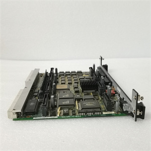
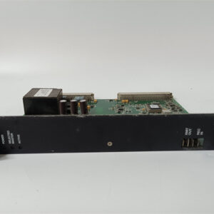
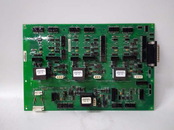
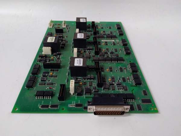
The GE IS210AEDBH4AGD is a high-density analog I/O module within the GE Mark VI/Mark VIe Turbine Control Systems, designed for Level 2 (Control) or Level 3 (Operations) of the Purdue Model in industrial automation. It resides in turbine control cabinets (mounted on Mark VI/Mark VIe control racks) and serves as the bridge between field devices (e.g., thermocouples, pressure transmitters, control valves) and the Mark VI/Mark VIe controller, connecting:
-
Field Devices: Receives analog signals (e.g., temperature from thermocouples, pressure from transmitters) via screw terminals or pre-wired cables.
-
Mark VI/Mark VIe Controller: Transmits digitized data to the controller via the VME backplane for real-time process control (e.g., adjusting fuel flow, turbine speed).
-
Actuators: Sends analog control signals (e.g., 4-20mA to control valves) to adjust process parameters.
Upstream Signal Reception
Receives analog signals from field devices (e.g., 4-20mA from pressure transmitters, thermocouple signals from temperature sensors). The module uses low-noise amplifiers to condition the signals (reduce noise) and 16-bit A/D converters to convert analog signals to digital data.
Downstream Communication
Transmits digitized data to the Mark VI/Mark VIe controller via the VME backplane. The controller uses this data for:
-
Real-Time Monitoring: Displaying process variables (e.g., turbine temperature, pressure) on the operator interface.
-
Process Control: Adjusting control valves, fuel flow, or turbine speed to maintain optimal operating conditions.
-
Fault Detection: Triggering alarms if parameters exceed predefined limits (e.g., high temperature, low pressure).
Operational Advantages
-
High Density: Combines 16 analog inputs and 8 analog outputs in one module, reducing the number of hardware components in control cabinets.
-
Precision: 16-bit resolution and ±0.05% accuracy ensure reliable measurement and control of critical turbine parameters.
-
Hot-Swappable: Allows technicians to replace the module without shutting down the system, minimizing downtime.
-
Compatibility: Seamlessly integrates with Mark VI/Mark VIe controllers, eliminating the need for custom interfaces.

GE IS210AEDBH4AGD
Core Technical Specifications
|
Attribute
|
Specification
|
|---|---|
|
Product Type
|
High-Density Analog Input/Output (I/O) Module
|
|
Part Number
|
IS210AEDBH4AGD
|
|
System Platform
|
GE Mark VI/Mark VIe Turbine Control Systems
|
|
Analog Inputs
|
16 channels (4-20mA, 0-10V, thermocouples (J/K/T/E/R/S/B), RTDs (Pt100, Pt1000))
|
|
Analog Outputs
|
8 channels (4-20mA, 0-10V)
|
|
Resolution
|
16-bit (current/voltage); 18-bit (thermocouple/RTD)
|
|
Accuracy
|
±0.05% of full scale (current/voltage); ±0.1°C (thermocouple); ±0.05°C (RTD)
|
|
Input Impedance
|
250Ω (4-20mA); >10MΩ (voltage); 100Ω (RTD)
|
|
Output Load Capacity
|
500Ω (4-20mA); 10kΩ (0-10V)
|
|
Power Supply
|
24V DC (±10%); isolated
|
|
Power Consumption
|
5W (typical)
|
|
Communication Interface
|
VME backplane (to controller); Ethernet (diagnostics)
|
|
Isolation
|
2500V AC channel-to-channel; 3000V AC channel-to-ground; 1500V AC input-to-output
|
|
Operating Temperature
|
-40°C to +70°C (extended industrial range)
|
|
Storage Temperature
|
-40°C to +85°C
|
|
Humidity
|
5–95% non-condensing
|
|
Dimensions (W×H×D)
|
~20 cm × 20 cm × 10 cm (approximate; varies by assembly)
|
|
Weight
|
~1.5 kg (3.3 lbs)
|
|
Certifications
|
CE, UL, RoHS (compliant with EU/US/Canadian standards)
|
Customer Value & Operational Benefits
Enhanced Turbine Reliability
The IS210AEDBH4AGD’s high-precision measurement and fault detection capabilities reduce the risk of turbine damage from overheating, overpressure, or incorrect fuel flow. A power plant using the module reported a 30% reduction in unplanned downtime due to early detection of temperature anomalies.
Reduced Maintenance Costs
The module’s hot-swap design allows technicians to replace it in minutes without shutting down the turbine. A chemical plant using the IS210AEDBH4AGD cut maintenance downtime by 40% compared to traditional non-hot-swappable I/O modules.
Cost-Effective Integration
Compatible with GE Mark VI/Mark VIe systems and third-party field devices (e.g., Siemens sensors, ABB actuators), the IS210AEDBH4AGD eliminates the need for custom signal conditioners. A water treatment plant using the module saved $10,000 in integration costs by retaining its existing Mark VI infrastructure.
Improved Process Visibility
The module’s real-time data transmission to the Mark VI/Mark VIe controller enables operators to monitor process variables and adjust parameters proactively. A gas turbine plant using the IS210AEDBH4AGD improved energy efficiency by 10% by optimizing fuel flow based on temperature data.
GE IS210AEDBH4AGD
Field Engineer’s Notes (From the Trenches)
When installing the IS210AEDBH4AGD, always use shielded twisted-pair cables for analog signals—unshielded cables can pick up electromagnetic interference (EMI) from nearby motors or power lines, leading to signal distortion. I once saw a site where a technician used unshielded cables, resulting in a 15% error rate in temperature measurements. Switching to shielded cables eliminated the problem immediately.Another gotcha: verify the signal type configuration—the module defaults to 4-20mA, but if you’re using thermocouples or RTDs, you must adjust the settings via the Mark VI/Mark VIe controller’s software (e.g., ToolboxST). I’ve fixed countless “signal out of range” errors by forgetting to modify the signal type.If the module’s fault LED illuminates, check the field device wiring—the most common cause is an open or short circuit in the sensor wiring. Use a multimeter to test the resistance of the sensor (e.g., 100 ohms for Pt100 RTD at 0°C) and verify it matches the expected value.
Real-World Applications
-
Power Generation:A coal-fired power plant uses the IS210AEDBH4AGD to monitor the temperature of 16 turbine bearings and control the fuel flow to the boiler. The module’s 16-bit resolution ensures accurate temperature measurement (±0.1°C), allowing the controller to adjust the fuel flow and maintain optimal turbine efficiency.
-
Gas Turbines:A natural gas power plant uses the IS210AEDBH4AGD to monitor the pressure of the gas inlet and control the turbine speed. The module’s 4-20mA outputs send signals to the fuel valves, adjusting the gas flow to maintain a constant turbine speed (e.g., 3000 RPM).
-
Combined-Cycle Plants:A combined-cycle power plant uses the IS210AEDBH4AGD to synchronize data between the gas turbine, steam turbine, and heat recovery steam generator (HRSG). The module’s high density (16 inputs, 8 outputs) reduces the number of modules needed in the control cabinet, saving space and cost.
High-Frequency Troubleshooting FAQ
Q: What does the fault LED indicate on the GE IS210AEDBH4AGD?
A: The fault LED indicates a critical error, such as:
-
Open/Short Circuit: A field device (e.g., sensor) is disconnected or shorted (check the sensor’s resistance with a multimeter);
-
Signal Out of Range: The input signal exceeds the module’s specified range (e.g., 25mA for a 4-20mA input);
-
Module Fault: The internal A/D converter or power supply is faulty (replace the module).
Q: Can the IS210AEDBH4AGD be used with non-GE controllers?
A: No, the IS210AEDBH4AGD is designed exclusively for GE Mark VI/Mark VIe systems. Non-GE controllers may not provide the correct backplane signals or power supply, leading to module failure.
Q: How do I configure the signal type on the IS210AEDBH4AGD?
A: Use GE’s ToolboxST software to configure the signal type:
-
Open ToolboxST: Launch the software and connect to the Mark VI/Mark VIe controller.
-
Select the IS210AEDBH4AGD: Navigate to the “I/O Configuration” tab and select the module.
-
Set Signal Type: Choose the correct signal type (e.g., 4-20mA, thermocouple) for each channel.
-
Save Configuration: Click “Save” to apply the changes to the module’s memory.
Q: Why is the IS210AEDBH4AGD’s signal unstable?
A: Check three things first:
-
Cables: Ensure the shielded twisted-pair cables are not damaged (check for cuts or breaks);
-
Grounding: Verify the shield is grounded at the module end (not at the field device) to minimize EMI;
-
Field Device: Ensure the field device (e.g., sensor) is not faulty (test with a multimeter).
Commercial Availability & Pricing
Please note: The listed price is not the actual final price. It is for reference only and is subject to appropriate negotiation based on current market conditions, quantity, and availability.