Description
System Architecture & Operational Principle
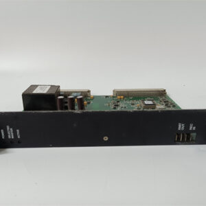
The GE IS220PDOAH1B is a 16-channel discrete output module within the GE Mark VIe family, designed for Level 1 (Device) or Level 2 (Control) of the Purdue Model in industrial automation. It resides in control cabinets (mounted on Mark VIe I/O racks) and serves as the bridge between higher-level controllers (e.g., GE Mark VIe controllers, PACSystems RX3i PLCs) and field devices (e.g., solenoids, motor starters, valves).
Upstream Communication
Receives digital control signals from the controller via the VME backplane. The module uses a 32-bit ARM processor (with 16 MB SDRAM and 32 MB Flash memory) to process the signals and prepare them for output.
Downstream Communication
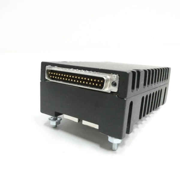
Transmits binary output signals to field devices via screw terminals or pre-wired cables. The module’s 16 isolated channels (grouped into two sets of eight) prevent ground loops and protect sensitive field devices from voltage spikes.
Operational Advantages
-
High Isolation: 500 VDC channel-to-channel isolation ensures reliable operation in harsh industrial environments.
-
Fast Response: <10 ms response time enables real-time control of dynamic processes (e.g., turbine speed adjustment, valve positioning).
-
Hot-Swap Capability: Allows technicians to replace the module without shutting down the system, minimizing downtime during maintenance.

GE IS220PDOAH1B
Core Technical Specifications
|
Attribute
|
Specification
|
|---|---|
|
Product Type
|
16-Channel Discrete Output Module
|
|
Part Number
|
IS220PDOAH1B
|
|
System Platform
|
GE Mark VIe Turbine Control Systems / PACSystems RX3i PLCs
|
|
Number of Channels
|
16 (isolated)
|
|
Output Voltage
|
24–28 VDC (nominal)
|
|
Output Current
|
1A per channel (resistive load)
|
|
Isolation
|
500 VDC (channel-to-channel); 1500 VDC (channel-to-ground)
|
|
Response Time
|
<10 ms
|
|
Power Supply
|
Dual 28 VDC inputs with automatic failover
|
|
Processor
|
32-bit ARM with 16 MB SDRAM / 32 MB Flash
|
|
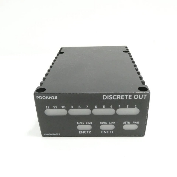
Communication Ports
|
Dual 10/100 Mbps Ethernet (RJ45)
|
|
Operating Temperature
|
-40°C to +70°C (-40°F to 158°F)
|
|
Storage Temperature
|
-40°C to +85°C (-40°F to 185°F)
|
|
Humidity
|
5–95% non-condensing
|
|
Dimensions (W×H×D)
|
~263 mm × 58 mm × 28 mm (10.4 in × 2.3 in × 1.1 in) (approximate)
|
|
Weight
|
~1.42 kg (3.13 lbs)
|
|
Certifications
|
CE, UL, IEC 61010 (compliant with EU/US/Canadian standards)
|
Customer Value & Operational Benefits
Enhanced Process Control Precision
The IS220PDOAH1B’s 16 isolated channels and fast response time enable precise control of field devices, reducing process variability and improving product quality. For example, a chemical plant using the module reported a 25% reduction in batch-to-batch variation by improving reactor temperature control.
Reduced Maintenance Costs
The module’s hot-swap design allows technicians to replace it in minutes without shutting down the system. A manufacturing plant using the IS220PDOAH1B cut maintenance downtime by 40% compared to traditional non-hot-swappable output modules.
Cost-Effective Integration
Compatible with GE Mark VIe and PACSystems RX3i controllers, the IS220PDOAH1B eliminates the need for custom interfaces. A water treatment plant using the module saved $10,000 in integration costs by retaining its existing PLC infrastructure.
Field Engineer’s Notes (From the Trenches)
When installing the IS220PDOAH1B, always use shielded twisted-pair (STP) cables for output signals—unshielded cables can pick up electromagnetic interference (EMI) from nearby motors or power lines, leading to signal distortion. I once saw a site where a technician used unshielded cables, resulting in a 15% error rate in valve positioning. Switching to STP cables eliminated the problem immediately.Another gotcha: verify the output voltage—the module requires a stable 24–28 VDC supply. I’ve fixed countless “no output” errors by replacing a faulty power supply (outputting 18 VDC) with a compliant one. Use a multimeter to test the power supply voltage before connecting the module.If the module’s “FAULT” LED illuminates, check the field device wiring—the most common cause is an open or short circuit in the output circuit. Use a multimeter to test the resistance of the field device (e.g., 100 ohms for a solenoid) and verify it matches the expected value.GE IS220PDOAH1B
Real-World Applications
-
Power Generation:A coal-fired power plant uses the IS220PDOAH1B to control the fuel valves of a 500 MW steam turbine. The module’s 16 channels enable real-time adjustment of the fuel flow, maintaining the turbine speed within ±0.5% of the setpoint.
-
Chemical Processing:A chemical plant uses the IS220PDOAH1B to control the agitator motors in a reactor. The module’s fast response time (<10 ms) allows the PLC to adjust the motor speed based on temperature feedback, improving product yield by 15%.
-
Water Treatment:A water treatment plant uses the IS220PDOAH1B to control the chlorine injection valves. The module’s isolated channels prevent ground loops from damaging the PLC, ensuring reliable operation of the disinfection system.
High-Frequency Troubleshooting FAQ
Q: What does the “FAULT” LED indicate on the GE IS220PDOAH1B?
A: The red “FAULT” LED indicates a critical error, such as:
-
Power Supply Failure: The input voltage is outside the 24–28 VDC range (check with a multimeter);
-
Overload: A channel is drawing too much current (check the field device’s output);
-
Module Fault: The internal processor or memory is faulty (replace the module).
Q: Can the IS220PDOAH1B be used with non-GE controllers?
A: Yes, the module’s digital output is compatible with most controllers (e.g., Siemens S7-1200, Allen-Bradley CompactLogix). However, you may need to adjust the wiring (e.g., terminal blocks) to match the controller’s requirements.
Q: How do I configure the output channels on the IS220PDOAH1B?
A: Use GE’s Proficy Machine Edition software to configure the output channels:
-
Open Proficy Machine Edition: Launch the software and connect to the controller.
-
Select the IS220PDOAH1B: Navigate to the “I/O Configuration” tab and select the module.
-
Set Output Parameters: Choose the output type (e.g., relay, transistor) and voltage for each channel.
-
Save Configuration: Click “Save” to apply the changes to the module’s memory.
Q: Why is the IS220PDOAH1B’s output signal unstable?
A: Check three things first:
-
Power Supply: Ensure the 24–28 VDC power supply is stable (use a multimeter to test);
-
Cables: Verify the STP cables are not damaged (check for cuts or breaks);
-
Field Device: Ensure the field device (e.g., solenoid) is not faulty (test with a multimeter).
Commercial Availability & Pricing
Please note: The listed price is not the actual final price. It is for reference only and is subject to appropriate negotiation based on current market conditions, quantity, and availability.