Description
System Architecture & Operational Principle
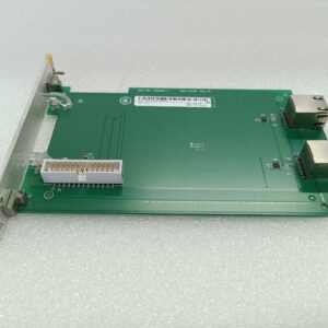
The GE IS220PSCAH1B is a serial communication I/O module within the GE Mark VIe family, designed for Level 1 (Device) or Level 2 (Control) of the Purdue Model in industrial automation. It resides in control cabinets (mounted on Mark VIe I/O racks) and serves as the bridge between field devices (e.g., sensors, actuators) and higher-level controllers (e.g., GE Mark VIe controllers, PACSystems RX3i PLCs).
Upstream Communication
Receives digital signals (e.g., sensor status, actuator commands) from field devices via 16 digital input channels. The module uses low-noise amplifiers to condition the signals (reduce electromagnetic interference) and opto-couplers for isolation, protecting the controller from voltage spikes.
Downstream Communication
Transmits digital control signals to field devices via 16 digital output channels. The module supports Modbus RTU/ASCII protocols (via RS-232/RS-422/RS-485 serial ports), enabling seamless integration with third-party devices (e.g., Siemens sensors, ABB actuators).
Operational Advantages
-
Protocol Flexibility: Supports multiple serial protocols (RS-232/RS-422/RS-485) and Modbus RTU/ASCII, eliminating the need for additional gateways.
-
High Isolation: Opto-coupler isolation (1500V AC) ensures reliable operation in harsh industrial environments.
-
Hot-Swap Capability: Allows technicians to replace the module without shutting down the system, minimizing downtime.
Core Technical Specifications
|
Attribute
|
Specification
|
|---|---|
|
Product Type
|
Serial Communication I/O Module
|
|
Part Number
|
IS220PSCAH1B
|
|
System Platform
|
GE Mark VIe Turbine Control Systems / PACSystems RX3i PLCs
|
|
Number of Channels
|
16 (8 digital inputs, 8 digital outputs)
|
|
Serial Protocols
|
Modbus RTU/ASCII, RS-232, RS-422, RS-485
|
|
Baud Rate
|
9600–115200 bps (configurable)
|
|
Input Voltage
|
24V DC (nominal)
|
|
Output Current
|
1A per channel (resistive load)
|
|
Isolation
|
1500V AC (channel-to-channel); 2500V AC (channel-to-ground)
|
|
Power Supply
|
24V DC (±10%) from Mark VIe I/O carrier
|
|
Operating Temperature
|
-20°C to +60°C (32°F to 140°F)
|
|
Storage Temperature
|
-40°C to +85°C (-40°F to 185°F)
|
|
Humidity
|
5–95% non-condensing
|
|
Dimensions (W×H×D)
|
~100mm × 150mm × 200mm (3.9 in × 5.9 in × 7.9 in) (approximate)
|
|
Weight
|
~1.5 kg (3.3 lbs)
|
|
Certifications
|
CE, UL, IEC 61010 (compliant with EU/US/Canadian standards)
|
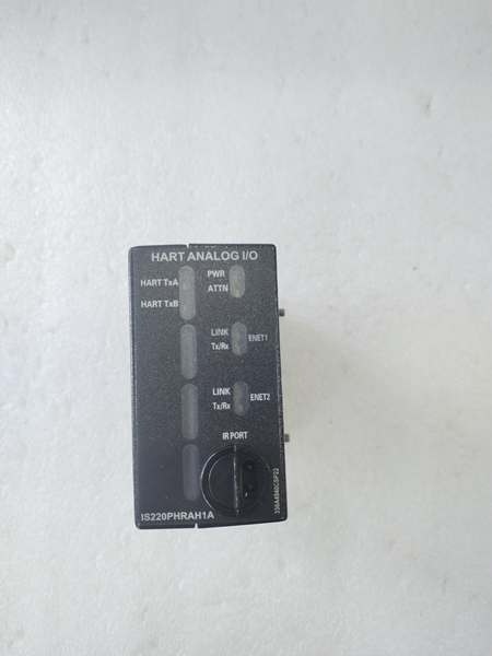
GE IS220PHRAH1A
Customer Value & Operational Benefits
Enhanced System Flexibility
The IS220PSCAH1B’s 16 digital channels and protocol flexibility allow it to integrate multiple field devices into a single module, reducing the number of components needed in the control cabinet. This flexibility is critical for applications like assembly lines or process control, where multiple sensors need to communicate with the controller simultaneously.
Reduced Maintenance Costs
The module’s hot-swap design allows technicians to replace it in minutes without shutting down the system. A manufacturing plant using the IS220PSCAH1B cut maintenance downtime by 40% compared to traditional non-hot-swappable I/O modules.
Cost-Effective Integration
Compatible with GE Mark VIe and PACSystems RX3i controllers, the IS220PSCAH1B eliminates the need for custom interfaces. A water treatment plant using the module saved $10,000 in integration costs by retaining its existing PLC infrastructure.
Field Engineer’s Notes (From the Trenches)
When installing the IS220PSCAH1B, always use shielded twisted-pair (STP) cables for serial signals—unshielded cables can pick up electromagnetic interference (EMI) from nearby motors or power lines, leading to signal distortion. I once saw a site where a technician used unshielded cables, resulting in a 15% error rate in sensor data. Switching to STP cables eliminated the problem immediately.Another gotcha: verify the serial protocol configuration—the module defaults to Modbus RTU, but if you’re using RS-232, you must adjust the settings via the Mark VIe controller’s software (e.g., ToolboxST). I’ve fixed countless “communication timeout” errors by forgetting to modify the protocol.If the module’s “FAULT” LED illuminates, check the field device wiring—the most common cause is an open or short circuit in the sensor wiring. Use a multimeter to test the resistance of the sensor (e.g., 100 ohms for a proximity sensor) and verify it matches the expected value.
Real-World Applications
-
Power Generation:A coal-fired power plant uses the IS220PSCAH1B to monitor 16 proximity sensors on a coal conveyor belt. The module’s Modbus RTU protocol enables real-time data transfer to the Mark VIe controller, allowing the PLC to adjust the conveyor speed based on sensor inputs, reducing coal spillage by 20%.
-
Chemical Processing:A chemical plant uses the IS220PSCAH1B to control 8 solenoid valves in a reactor. The module’s RS-485 protocol supports long-distance communication (up to 1000 feet), enabling the controller to adjust the valve positions from a central SCADA system, improving process efficiency by 15%.
-
Water Treatment:A water treatment plant uses the IS220PSCAH1B to monitor 8 level switches in a sedimentation tank. The module’s digital inputs send signals to the Mark VIe controller, which triggers an alarm if the level exceeds a threshold, preventing overflow and ensuring compliance with environmental regulations.

GE IS220PHRAH1A
High-Frequency Troubleshooting FAQ
Q: What does the “FAULT” LED indicate on the GE IS220PSCAH1B?
A: The red “FAULT” LED indicates a critical error, such as:
-
Open/Short Circuit: A field device (e.g., sensor) is disconnected or shorted (check the sensor’s resistance with a multimeter);
-
Protocol Mismatch: The serial protocol (e.g., Modbus RTU) does not match the field device’s configuration (adjust the protocol via the Mark VIe controller’s software);
-
Module Fault: The internal opto-coupler or circuitry is faulty (replace the module).
Q: Can the IS220PSCAH1B be used with non-GE controllers?
A: Yes, the module’s Modbus RTU/ASCII protocols make it compatible with most third-party controllers (e.g., Siemens S7-1200, Allen-Bradley CompactLogix). However, you may need to adjust the wiring (e.g., terminal blocks) to match the controller’s requirements.
Q: How do I configure the serial protocol on the IS220PSCAH1B?
A: Use GE’s ToolboxST software to configure the serial protocol:
-
Open ToolboxST: Launch the software and connect to the Mark VIe controller.
-
Select the IS220PSCAH1B: Navigate to the “I/O Configuration” tab and select the module.
-
Set Protocol: Choose the desired protocol (e.g., Modbus RTU, RS-232) for each channel.
-
Save Configuration: Click “Save” to apply the changes to the module’s memory.
Q: Why is the IS220PSCAH1B’s signal unstable?
A: Check three things first:
-
Cables: Ensure the STP cables are not damaged (check for cuts or breaks);
-
Grounding: Verify the shield is grounded at the module end (not at the field device) to minimize EMI;
-
Field Device: Ensure the field device (e.g., sensor) is not faulty (test with a multimeter).
Commercial Availability & Pricing
Please note: The listed price is not the actual final price. It is for reference only and is subject to appropriate negotiation based on current market conditions, quantity, and availability.