Description
Detailed Parameter Table
| Parameter name | Parameter value |
| Product model | SR489 – P5 – LO – A20 – E |
| Manufacturer | GE (General Electric) |
| Product category | Generator Management Relay |
| Series | SR489 |
| Function | Manages and protects generators, ensuring stable operation |
| Phase current inputs | P5 – 5 A phase CT secondaries |
| Control power range | LO – 20 – 60 VDC / 20 – 48 VAC at 20 – 48 Hz |
| Analog outputs | A20 – 4 – 20 mA analog outputs |
| Display | E – Enhanced 40 – character LCD |
| Protection features | Overload, short – circuit, under – voltage, over – voltage, high – set phase overcurrent (with trip function), phase overcurrent voltage restraint (programmable fixed characteristic) |
| Communication interfaces | 2 RS485 ports supporting Modbus RTU or DNP 3.0 protocols (up to 19200 bps), also has an RS232 port on the front panel |
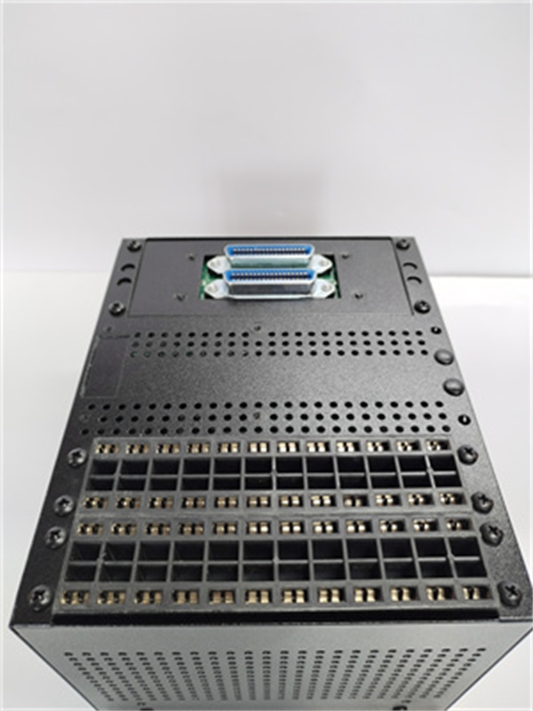
| Inputs | 7 CT inputs for three – phase output / three – phase neutral line and ground current detection; 4 isolated 4 – 20 mA analog inputs; 7 assignable digital inputs; 12 RTD inputs (field – programmable) |
| Outputs | 6 output relays |
| Frequency operating range | 25, 50, or 60 Hz |
| Frequency parameter range | 0.00 – 90.00 Hz |
| Zero line voltage (3rd) parameter range | 0 – 25000 V |
| Power factor parameter range | 0.01 – 1.00 lead / lag |
| Reactive power (mvar) parameter range | – 2.00 – 2.00 times the rated voltage |
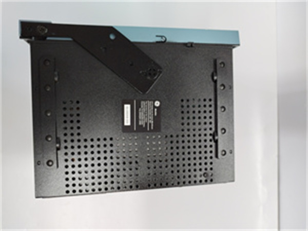
| Dimensions | 21.6 cm (length) x 22.4 cm (width) x 25.2 cm (height) |
| Weight | Approximately 10 kg (shipping weight) |
| Warranty | 12 months |
| Certifications | Complies with relevant industry standards, inputs comply with SWC, C37.990 EMI, RFI interference immunity |
| Mounting | Likely panel or rack – mountable (compact structure for easy installation) |

GE SR489-P5-LO-A20-E
Product Introduction
The GE SR489 – P5 – LO – A20 – E is a sophisticated generator management relay within GE’s SR489 series. Engineered to meet the diverse needs of modern power generation setups, it plays a pivotal role in safeguarding and optimizing generator performance. This relay combines a comprehensive set of protection, monitoring, and control functions, making it an ideal choice for a wide range of applications, from small – scale industrial backup power systems to larger – scale power generation plants. Its enhanced 40 – character LCD display provides clear and detailed information, while its multiple input and output options enable seamless integration into various power generation architectures.
Core Advantages and Technical Highlights
Comprehensive Protection Mechanisms: The SR489 – P5 – LO – A20 – E comes equipped with a robust set of protection features. Overload protection safeguards the generator from excessive current draw over an extended period, which could be caused by increased load demands or inefficiencies in the connected electrical systems. Short – circuit protection acts rapidly to isolate the generator in case of a direct short between conductors, preventing significant damage. Under – voltage and over – voltage protection are crucial for maintaining the integrity of the generator’s electrical components. When the voltage drops below or rises above safe levels, the relay takes appropriate action, such as tripping the generator or adjusting its operation. The high – set phase overcurrent elements, with their trip function, can quickly respond to sudden surges in phase currents, while the programmable phase overcurrent voltage restraint ensures that the protection is tailored to the specific characteristics of the generator and its connected network. For instance, in a manufacturing plant where there are frequent changes in the electrical load due to the operation of heavy machinery, the overload and short – circuit protection of the SR489 – P5 – LO – A20 – E will protect the backup generator from potential damage caused by sudden power surges.
Flexible and Precise Monitoring: With its multiple input options, including 7 CT inputs for three – phase and ground current detection, 4 isolated 4 – 20 mA analog inputs, 7 assignable digital inputs, and 12 field – programmable RTD inputs, the relay can monitor a wide range of generator parameters. The RTD inputs, for example, can be used to monitor the temperature of critical generator components, such as the windings or bearings. By continuously monitoring these parameters, operators can detect early signs of wear, overheating, or other potential issues. The 4 – 20 mA analog outputs also allow for easy integration with other monitoring and control systems, providing a standardized way to transmit data. In a power generation plant, the relay’s monitoring capabilities can be used to track the performance of the generators over time, enabling predictive maintenance and optimizing overall power generation efficiency.
Efficient Communication and Connectivity: The two RS485 communication ports, supporting Modbus RTU or DNP 3.0 protocols at speeds up to 19200 bps, enable seamless integration with supervisory control and data acquisition (SCADA) systems, as well as other intelligent devices in the power network. This allows for remote monitoring and control of the generator, reducing the need for on – site presence and improving operational efficiency. The additional RS232 port on the front panel provides an alternative communication option for local configuration and troubleshooting. In a large – scale power distribution network, the relay’s communication capabilities can be used to integrate data from multiple generators into a central control system, enabling better management of the overall power grid.
User – Friendly Interface and Configuration: The enhanced 40 – character LCD display, along with the front – panel numeric keypad, status indicators, and control keys (such as reset, enter, menu, menu up, and menu down), makes it easy for operators to view value messages, diagnostics, and set values without the need for an external computer. This intuitive interface simplifies the configuration process, allowing users to quickly adjust the relay’s settings according to the specific requirements of their power generation applications. Additionally, the relay can be configured using the Enervista software, providing an alternative, more detailed way to customize its functions. In a small – scale power generation facility, an operator can easily use the front – panel interface to check the generator’s status and make any necessary adjustments, ensuring smooth operation.
Typical Application Scenarios
Small – to Medium – Scale Industrial Plants: In industrial settings where backup power is crucial, such as manufacturing plants, the SR489 – P5 – LO – A20 – E can manage and protect the backup generators. It ensures that the generators start up quickly and smoothly during power outages, protect them from overloading during operation, and synchronize them with the plant’s electrical system. For example, in a textile factory, the relay can safeguard the backup generator from voltage fluctuations and overloads caused by the operation of multiple high – power machines, ensuring continuous production.
Commercial Buildings with Backup Power: Many commercial buildings, such as hospitals, hotels, and shopping malls, rely on backup generators to maintain essential services during grid outages. The SR489 – P5 – LO – A20 – E can be used to manage these backup generators, providing reliable protection and control. In a hospital, for instance, the relay ensures that the backup generator supplies stable power to life – support systems, medical equipment, and lighting, even during extended power outages.
Renewable Energy Micro – Grids: In small – scale renewable energy installations, such as a community – based wind or solar power micro – grid, the SR489 – P5 – LO – A20 – E can manage the generators or inverters. It synchronizes the power generated by renewable sources to the local grid, protects the equipment from electrical faults, and controls their operation based on the availability of renewable energy and the demand on the grid. In a small wind – powered micro – grid in a rural area, the relay can ensure that the power generated by the wind turbines is smoothly integrated into the local power network, while protecting the turbines’ generators from over – voltage and over – current conditions.
GE SR489-P5-LO-A20-E
Related Model Recommendations
GE SR489 – P1 – HI – A20 – E: This model has different current input ratings (P1 – 1 A phase CT secondaries) and a higher control power range (HI – 90 – 300 VDC / 70 – 265 VAC at 48 – 62 Hz). It can be a suitable alternative for applications where the power requirements and frequency range are different from those of the SR489 – P5 – LO – A20 – E. In a large – scale power generation plant with higher – voltage and higher – current generators, the SR489 – P1 – HI – A20 – E may be more appropriate.
GE Communication Gateway for SR489 Series: This dedicated communication gateway can further enhance the communication capabilities of the SR489 – P5 – LO – A20 – E. It can support more complex communication protocols, enabling better integration with advanced SCADA systems or cloud – based monitoring platforms. In a large – scale power utility network that requires centralized data management and advanced analytics, the communication gateway can help in collecting and analyzing data from multiple SR489 – series relays, improving overall grid management.
GE Generator Monitoring Software: This software works in tandem with the SR489 – P5 – LO – A20 – E to provide a more user – friendly interface for monitoring and analyzing the generator’s performance data. Operators can use this software to view real – time trends, generate reports, and set up alerts for abnormal conditions. In a power plant’s control center, the generator monitoring software allows operators to efficiently manage multiple generators equipped with SR489 – series relays, optimizing the power generation process.
Installation, Commissioning and Maintenance Instructions
Installation Preparation: Before installation, ensure that the power supply to the generator and related circuits is completely disconnected to avoid electrical accidents. Select an installation location that is clean, dry, and free from excessive vibration and strong electromagnetic interference. Verify that the control power supply voltage is within the LO range (20 – 60 VDC / 20 – 48 VAC at 20 – 48 Hz). Given its likely panel or rack – mountable design with a compact structure, use the appropriate mounting hardware provided to securely install the relay. Leave sufficient clearance around the relay for proper ventilation and easy access during future maintenance.
Commissioning: After installation, carefully connect the current transformers (CTs) and voltage transformers (VTs) to the relay’s input terminals as per the detailed wiring diagram in the product documentation. Connect the analog output cables to the relevant devices. Power on the control supply and use the enhanced 40 – character LCD display to configure the relay’s parameters. Set the protection thresholds, control settings, communication protocols, and other relevant parameters according to the specific requirements of the power generation system. Conduct comprehensive functional tests for each protection and control function by simulating various operating conditions, such as starting the generator, applying load, and introducing faults. Verify that the relay operates correctly and sends out appropriate signals. Check the communication links to ensure accurate data transmission to the connected monitoring systems.
Maintenance Suggestions: Regularly conduct visual inspections of the relay to check for any loose connections, dust accumulation, or physical damage. Periodically clean the relay’s exterior and ventilation slots using compressed air to maintain proper cooling and prevent the entry of dust and debris. Use calibrated test equipment at regular intervals to verify the accuracy of the relay’s measurements. Review the self – diagnostic reports and fault records stored in the relay to identify any recurring issues or potential problems. Keep the relay’s firmware up – to – date by checking GE’s official website for the latest software updates. In case of a fault or malfunction, refer to the detailed user manual or contact GE’s technical support team for prompt troubleshooting and resolution.
Service and Guarantee Commitment
GE offers a 12 – month warranty for the SR489 – P5 – LO – A20 – E, covering manufacturing defects and component failures under normal operating conditions. The company’s global technical support team is available to provide assistance with installation, commissioning, and troubleshooting. Customers can access a wealth of resources, including detailed user manuals, technical specifications, and software updates, through GE’s online portal. For critical applications, GE may also offer extended warranty options and on – site service agreements to ensure the relay’s optimal performance and minimize downtime. In the event of a warranty claim, GE will promptly arrange for the repair or replacement of the faulty unit, ensuring customer satisfaction and the continuous, reliable operation of the generator management system.