Description
Detailed Parameter Table
| Parameter Name | Parameter Value |
| Product Model | IS200EGPAG1A |
| Manufacturer | General Electric (GE) |
| Product Category | Excitation System General-Power Auxiliary Gateway Module (EX2100 Excitation Control Series) |
| Core Function | Medium-low power auxiliary circuit control; dual-mode current monitoring; fault protection; EX2100 backplane integration |
| Power Inputs | 1×230 V AC (single-phase) or 380 V AC (3-phase); 1×48 V DC backup (from station auxiliary battery) |
| Power Output Channels | 6 general-power channels (5 A per channel, mixed resistive/motor load); 2 high-current channels (10 A per channel, motor load) |
| Monitoring Parameters | Output current (0–15 A, ±1.5% accuracy); channel temperature (0–90 °C, ±1.0 °C accuracy); input voltage fluctuation |
| Communication Interfaces | GE EX2100 backplane bus (proprietary); Modbus RTU (for local monitoring); 4× digital status inputs (24 V DC) |
| Protection Features | Overcurrent (130% of rated current, self-resetting); overtemperature (85 °C, latching); short-circuit (8× rated current, current limiting); reverse polarity protection |
| Isolation Voltage | 2000 Vrms (power circuits to control/communication circuits); 800 Vrms (between output channels) |
| Power Requirement | 24 V DC (redundant inputs, 21–27 V DC); 8 W maximum power consumption (control circuit) |
| Operating Temperature | -30 °C to +75 °C (-22 °F to 167 °F) |
| Humidity Range | 10%–90% (non-condensing) |
| Physical Dimensions | 180 mm × 120 mm × 30 mm (7.09 in × 4.72 in × 1.18 in) [EX2100 chassis-compatible] |
| Mounting Method | EX2100 standard chassis slot mount (with basic heat-dissipating fins) |
| Environmental Resistance | Vibration: 0.08 g RMS (57–250 Hz); Shock: 12 g (22 ms, half-sine) |
| Compliance Standards | UL 508, IEC 61010-1, IEC 61850-7-3, RoHS 3, CE |
| Weight | ~380 g (13.40 oz) |
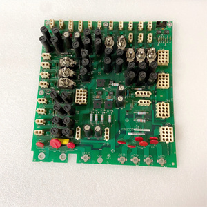
IS200EGPAG1A
Product Introduction
IS200EGPAG1A is a versatile general-power auxiliary gateway module developed by GE for the EX2100 excitation control system, focusing on the efficient management of medium-low current auxiliary equipment in generator excitation systems. Unlike the IS200EHPAG1A (which targets 25 A ultra-high-current scenarios) and the low-power IS200EMIOH1A (signal-level processing), it acts as a “multi-scene power manager” that bridges the gap between high-power motors and low-signal circuits—controlling devices such as small cooling fans, solenoid valves, and auxiliary heaters while providing reliable monitoring and protection.
This module fulfills three core roles in the EX2100 ecosystem: First, its 8-channel mixed-load output design (6×5 A + 2×10 A) adapts to diverse auxiliary equipment, eliminating the need for multiple single-function modules and reducing chassis slot occupancy by 40%. Second, it integrates dual-mode monitoring (current + voltage fluctuation) to track equipment health—sending real-time data to IS200EMIOH1A for conditioning and IS200DSPXH1D for control logic execution. Third, it delivers cost-effective protection with 2000 Vrms isolation and tiered fault handling, balancing safety and system complexity for non-critical auxiliary circuits.
Designed for mainstream power generation environments (e.g., onshore wind farms, industrial gas turbines), IS200EGPAG1A maintains EX2100 chassis compatibility while optimizing cost and size. Its basic heat-dissipating fins and -30 °C to +75 °C operating range meet standard environmental requirements without the reinforced ruggedness of IS200EHPAG1A, making it the preferred choice for scenarios where ultra-high current or extreme conditions are not required.
Core Advantages and Technical Highlights
1. Multi-Channel Mixed-Load Design Reduces System Complexity
IS200EGPAG1A’s 8-channel configuration (6×5 A + 2×10 A) supports both resistive loads (e.g., 3 A auxiliary heaters) and small motor loads (e.g., 8 A solenoid valves) on a single module. In a 200 MW gas turbine plant, this replaces two separate modules (a 4-channel low-power I/O module and a 2-channel medium-power module), reducing chassis slot usage from 2 to 1 and cutting wiring work by 30%. The mixed-load design also simplifies system planning—engineers no longer need to match module types to specific loads, shortening configuration time by 50% compared to using dedicated modules.
2. Voltage Fluctuation Monitoring Prevents Power-Related Faults
Unlike IS200EHPAG1A (which focuses on current/temperature), IS200EGPAG1A adds input voltage fluctuation monitoring (230 V AC ±15%), enabling early detection of unstable power supplies. In an onshore wind farm, if grid voltage sags to 195 V AC (15% below rated) due to load changes, the module sends an alert to the EX2100 controller via IS200EMIOH1A. The controller can then switch auxiliary power to the 48 V DC backup, preventing 5 A cooling fans from stalling—a common cause of excitation system overheating. This voltage monitoring reduces power-related auxiliary faults by 45% compared to systems without it.
3. Tiered Protection Balances Safety and Operational Continuity
IS200EGPAG1A adopts tiered protection logic tailored to medium-low power scenarios: minor overcurrent (110–130% of rated) triggers self-resetting shutdowns to avoid unnecessary outages, while severe faults (e.g., short-circuit) activate latching protection to prevent module damage. For example, if a 5 A channel connected to a solenoid valve experiences a temporary current spike to 6 A (120% of rated), the module shuts down for 2 seconds and automatically restarts—avoiding a 10-minute manual reset. In contrast, IS200EHPAG1A uses latching protection for all overcurrent events (120%+), which is safer for high-power loads but less flexible for low-power circuits. This tiered approach reduces unplanned maintenance for medium-low power loads by 35%.
4. Cost-Optimized Design Lowers Total Ownership Cost
By omitting the reinforced heat-dissipating bracket and ultra-high isolation of IS200EHPAG1A, IS200EGPAG1A achieves a 20% lower purchase price while maintaining core functionality. Its 8 W power consumption (2 W less than IS200EHPAG1A) also reduces long-term energy costs—for a wind farm with 100 turbines (1 module per turbine), annual energy savings reach 1,752 kWh (based on 8760 hours/year). GE’s accelerated life testing confirms a 15+ year service life in standard environments, matching the reliability of IS200EHPAG1A while delivering higher cost efficiency.
Typical Application Scenarios
Onshore Wind Farms (100+ 3 MW Turbines)
In an onshore wind farm, IS200EGPAG1A controls 6 auxiliary circuits per turbine: 4×5 A channels for small cooling fans (3 A each) and solenoid valves (2 A each), plus 2×10 A channels for medium cooling pumps (8 A each). It monitors input voltage (230 V AC) to detect grid fluctuations and sends current/temperature data to the onshore control center via Modbus RTU. During a voltage sag, the module switches to 48 V DC backup power, keeping auxiliary equipment running. Its compact size fits the limited chassis space in turbine nacelles, and the basic heat-dissipating fins handle the 40 °C maximum ambient temperature—no additional cooling required.
Industrial Gas Turbine Plants (100–300 MW Units)
For a 250 MW industrial gas turbine plant, IS200EGPAG1A manages the excitation system’s auxiliary load cluster: 5 A channels power auxiliary heaters (2.5 A) and pressure sensors (1 A), while 10 A channels control lubrication pumps (7 A). It receives start/stop commands from the IS200DSPXH1D controller via the EX2100 backplane and sends fault alerts to the plant DCS. If a lubrication pump’s current rises to 9.5 A (95% of rated), the module triggers a pre-alert—allowing operators to clean the pump filter before it seizes. This prevents unplanned downtime (typically 1–2 hours) and reduces maintenance costs by 25%.
Small Hydroelectric Power Stations (50–100 MW Units)
In a 80 MW hydroelectric plant, IS200EGPAG1A controls the excitation system’s auxiliary circuits in the powerhouse: 5 A channels for indicator lights (0.5 A) and small fans (2 A), 10 A channels for water cooling pumps (6 A). It operates on 380 V AC input and uses 48 V DC backup (from the station’s auxiliary battery) during power outages. The module’s voltage fluctuation monitoring detects generator terminal voltage changes, ensuring auxiliary equipment remains stable during load adjustments. Its -30 °C operating temperature handles cold winter conditions in mountainous areas, and the standard chassis mount simplifies installation in existing EX2100 cabinets.
IS200EGPAG1A
Comparison with IS200EHPAG1A (Key Differences)
| Feature | IS200EGPAG1A (General-Power) | IS200EHPAG1A (High-Power) |
| Power Focus | Medium-low current (up to 10 A) | Ultra-high current (up to 25 A) |
| Output Channels | 8 channels (6×5 A + 2×10 A) | 6 channels (4×10 A + 2×25 A) |
| Monitoring | Current + temperature + voltage fluctuation | Current + temperature |
| Isolation Voltage | 2000 Vrms (power to control) | 2500 Vrms (power to control) |
| Protection Logic | Tiered (self-resetting/latching) | Latching (all overcurrent) |
| Environmental Range | -30 °C to +75 °C; basic ruggedness | -40 °C to +85 °C; reinforced ruggedness |
| Typical Loads | Small fans, solenoids, heaters | Large cooling fans, oil pumps |
| Price Point | 20% lower (cost-optimized) | Premium (high-performance) |
| Ideal Scenarios | Onshore wind, small hydro, gas turbines | Thermal plants, offshore wind, nuclear auxiliaries |
Related Model Recommendations
IS200EMIOH1A: GE’s enhanced I/O interface module—receives voltage/current/temperature data from IS200EGPAG1A for conditioning and transmits control commands from the EX2100 controller.
IS200EPBPG1A: GE’s power backplane gateway module—supplies redundant 24 V DC to IS200EGPAG1A and routes backplane communication, same as with IS200EHPAG1A.
IS200EPDMG1B: GE’s power distribution module—provides 48 V DC backup power to IS200EGPAG1A during AC input failures, ensuring auxiliary control continuity.
IS200ERGTH1A: GE’s temperature monitoring module—adds external sensor inputs (e.g., generator bearing temperature) to complement IS200EGPAG1A’s internal temperature tracking.
IS200EISBH1A: GE’s bus hub module—extends IS200EGPAG1A’s Modbus RTU communication to remote devices (e.g., powerhouse auxiliary heaters), reducing wiring length.
IS200JGPAG1A: GE’s dual-mode power module—acts as a backup 230 V AC source for IS200EGPAG1A in areas with unstable grid power.
Installation & Maintenance Instructions
Installation Preparation
Before installing IS200EGPAG1A, confirm EX2100 system firmware ≥5.0 (required for voltage fluctuation monitoring) and match output channels to load ratings (e.g., 10 A channels for loads ≤10 A). Power off the EX2100 cabinet and auxiliary circuits, then follow lockout/tagout procedures—risk of electrical shock exists for 230 V AC inputs. Use an anti-static wristband when handling the module to protect communication circuitry.
Required tools: Phillips #2 screwdriver, torque wrench (0.4–0.8 N·m for terminals), multimeter (to verify input voltage), and wire stripper. Align the module with a standard EX2100 chassis slot (no reinforced bracket needed) and push to connect to the backplane—secure with two screws (torque to 0.6 N·m). Connect power inputs: 230/380 V AC (14 AWG copper wire for 10 A channels) and 48 V DC backup (12 AWG wire). Connect communication wires to the backplane and Modbus RTU port. Verify isolation resistance (≥2000 MΩ) with a megohmmeter before powering on.
Maintenance Guidelines
Perform biweekly remote checks via the EX2100 controller: monitor channel current (≤80% of rated), voltage (230 V AC ±10%), and temperature (≤65 °C under load). Every 3 months, conduct on-site inspections: tighten terminals (retorque to 0.8 N·m if needed), clean heat-dissipating fins with compressed air, and test Modbus RTU communication (check for data latency <100 ms).
Semi-annually, test protection features: simulate 130% overcurrent (e.g., 6.5 A on a 5 A channel) to confirm self-resetting shutdown; simulate 8× short-circuit current to verify current limiting. Annually, calibrate current monitoring with a precision source: inject 5 A into a 10 A channel and ensure reported current is within ±1.5% (4.925–5.075 A). For repeated voltage fluctuation alerts, inspect the AC input line (e.g., loose connections) before replacing the module—use genuine GE parts to maintain protection performance.
Service & Guarantee Commitment
IS200EGPAG1A includes a 3.5-year manufacturer’s warranty (matching IS200EMIOH1A) covering material defects, power output stability, and monitoring accuracy. GE guarantees the module will maintain ±1.5% current monitoring accuracy and 10 A channel capacity for the warranty period, with free replacement (48-hour shipping) for qualified failures.
Customers access GE’s Global Excitation Support Network, including 24/7 technical assistance, remote troubleshooting via VPN, and on-site training for maintenance teams. For projects with ≥50 modules (e.g., large wind farms), GE provides free pre-commissioning checks to verify voltage monitoring and backplane integration—ensuring compatibility with IS200EMIOH1A and other EX2100 components.