Description
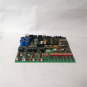
GE IS200JPDSG1ACB Mark VIe Power Drive Signal Module
Detailed Parameter Table
Parameter Name | Parameter Value ———|——– Product Model | **IS200JPDSG1ACB** Manufacturer | GE General Electric Product Category | Industrial Power Drive Signal Module Series | Mark VIe (Turbine Control System) Signal Type | Power Drive Input/Output, Analog/Digital Hybrid Analog Input Channels | 8 Differential Inputs (4-20mA, 0-10V) Analog Output Channels | 8 Isolated Outputs (4-20mA, 0-10V) Digital Input Channels | 16 Optically Isolated Inputs (24V DC) Digital Output Channels | 16 Relay Outputs (250V AC/30V DC) Drive Signal Bandwidth | 0-1kHz Accuracy | ±0.1% of Full Scale (Analog I/O) Isolation Voltage | 1500V AC (Channel to Channel, Power to Signal) Response Time | ≤1ms (Digital I/O), ≤5ms (Analog I/O) Protection Functions | Overcurrent, Short Circuit, Signal Overload, Reverse Polarity Operating Temperature | -10°C to 65°C Storage Temperature | -40°C to 85°C Protection Rating | IP20 (Module), NEMA 12 (Chassis Mount) Physical Dimensions | 150mm × 130mm × 35mm Certifications | UL 508, CE, CSA, IEC 61131-2 Communication Protocols | GE SRTP, PROFIBUS-DP (Drive Control Support)
Product Introduction
The **GE IS200JPDSG1ACB** is a high-performance power drive signal module developed for GE’s Mark VIe turbine control system, specializing in the conversion, processing, and transmission of power drive signals between the turbine control system and execution components. As a core link connecting the upper control unit and the lower power drive device in GE’s industrial drive portfolio, this module is mainly used to interface with turbine key execution components such as variable frequency drives (VFDs), servo valves, and power regulators. It can accurately collect the status feedback signal of the drive device and stably output the control signal of the upper system, realizing the closed-loop control of the turbine power drive link. Its hybrid analog/digital signal processing capability, fast response speed, and strong anti-interference performance make it an essential equipment for turbine speed regulation, valve control, and load adjustment systems in thermal power plants, hydropower plants, and industrial turbine application scenarios.
What distinguishes the **GE IS200JPDSG1ACB** is its integrated hybrid signal processing, precise drive control, and reliable protection mechanism—advantages that meet the core demand for high-precision and high-reliability signal transmission in turbine power drive control scenarios. Leveraging GE’s advanced drive signal processing technology, the module integrates independent analog and digital signal processing circuits, with each channel equipped with dedicated signal conditioning and isolation components to avoid mutual interference between different types of signals. The analog I/O accuracy reaches ±0.1% of full scale, ensuring the precise transmission of control signals such as valve opening and speed regulation; the digital I/O response time is less than 1ms, which can quickly capture the status of drive devices such as fault alarms. With 1500V AC high-voltage isolation and multi-level protection functions, it can effectively resist the strong electromagnetic interference generated by power drive equipment and avoid module damage caused by abnormal signals. By building a stable and accurate “signal bridge” between the control system and the drive device, it provides a solid guarantee for the precise control of the turbine.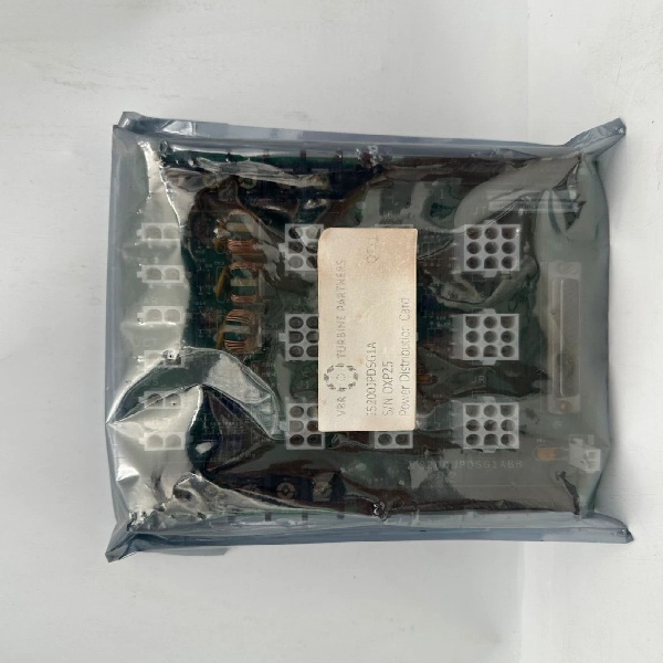
Core Advantages and Technical Highlights
Hybrid Analog/Digital Signal Integration: The **IS200JPDSG1ACB** integrates 8 analog input channels, 8 analog output channels, 16 digital input channels, and 16 digital output channels, realizing the integrated processing of turbine drive control-related signals. The analog channels support 4-20mA and 0-10V signal types, which are used to collect continuous status signals such as drive device current, voltage, and speed, and output continuous control signals such as valve opening and speed regulation. The digital channels adopt optical isolation and relay output designs, which are used to collect discrete signals such as drive device start/stop status and fault alarms, and output control signals such as device enable and emergency stop. The module’s internal logic processing unit can realize basic signal interlocking and conversion, reducing the computing pressure of the upper control module.
High-Precision Signal Processing and Fast Response: Each analog channel of the module is equipped with a 16-bit high-resolution ADC/DAC chip, with an accuracy of ±0.1% of full scale, which can accurately capture subtle changes in drive signals (such as a 0.02mA variation in servo valve control current). The analog signal response time is less than 5ms, ensuring that the control command can be quickly transmitted to the drive device. The digital input channel adopts a high-speed optical coupling circuit, with a response time of less than 1ms, which can immediately capture the fault signal of the drive device and feed it back to the upper system. The digital output channel uses high-reliability relays with a mechanical life of more than 10 million times, ensuring the stable output of control signals.
Comprehensive Protection and Anti-Interference Design: The module is equipped with a multi-level protection system for power drive scenarios, including analog output overcurrent protection (≥50mA per channel), digital output short-circuit protection, signal input overload protection (≥150% of full scale), and power supply reverse polarity protection. When an abnormal signal occurs, the module quickly cuts off the corresponding channel output and triggers an alarm, avoiding damage to the module and the connected drive device. The module adopts 1500V AC high-voltage isolation between channels and between power and signal, and integrates multi-layer EMI filtering circuits, complying with EN 61000-6-2 industrial immunity standards, which can effectively resist the electromagnetic interference generated by large power drive devices such as turbine variable frequency drives.
Seamless Integration with Drive Control Ecosystem: The **IS200JPDSG1ACB** is designed with a standard Mark VIe chassis mounting interface, which can be directly installed in the Mark VIe control cabinet and perfectly matched with the turbine control system. It communicates with the Mark VIe main control module (IS200MACCH1A/B) through GE SRTP high-speed protocol, realizing real-time synchronization of drive signal data. The module supports PROFIBUS-DP communication protocol, which can directly connect with mainstream power drive devices (such as GE PowerFlex series VFDs) without additional communication conversion modules. It supports online configuration and firmware update via Mark VIe Configuration Studio, and the channel parameters (signal type, range, protection threshold) can be flexibly set to adapt to different drive device requirements.
Typical Application Scenarios
In thermal power plant steam turbine speed regulation systems, the **IS200JPDSG1ACB** serves as the core signal interface module between the Mark VIe control system and the steam turbine governor. It collects analog signals such as governor servo valve current (4-20mA) and position feedback (0-10V) through analog input channels, and collects digital signals such as governor fault status and oil pressure switch status through digital input channels. At the same time, it outputs speed regulation control signals (4-20mA) to the servo valve through analog output channels, and outputs governor enable and reset signals through digital output channels. When the turbine load changes, the module quickly transmits the control command of the upper system to the governor, and feeds back the real-time status of the governor to the control system, realizing the precise adjustment of the turbine speed, with the speed control error within ±0.1rpm.
In industrial gas turbine fuel control systems (such as chemical and metallurgical plant gas turbines), the **IS200JPDSG1ACB** is responsible for the signal interaction between the Mark VIe control system and the fuel supply drive device. It collects analog signals such as fuel control valve opening feedback (4-20mA) and fuel pressure (0-10V) through analog input channels, and collects digital signals such as fuel pump running status and filter blockage alarm through digital input channels. It outputs fuel flow control signals (4-20mA) to the control valve through analog output channels, and outputs fuel pump start/stop control signals through digital output channels. The module’s fast response speed ensures that the fuel supply can be adjusted in time when the gas turbine load changes, avoiding excessive fuel consumption or insufficient combustion, and improving the operation efficiency and safety of the gas turbine.
In medium-sized hydropower plant turbine gate control systems, the **IS200JPDSG1ACB** undertakes the signal transmission task between the Mark VIe control system and the gate drive mechanism. It collects analog signals such as gate opening feedback (4-20mA) and drive motor current (0-10V) through analog input channels, and collects digital signals such as gate limit switch status and drive mechanism fault alarm through digital input channels. It outputs gate opening/closing control signals (4-20mA) to the drive servo valve through analog output channels, and outputs drive mechanism emergency stop signals through digital output channels. The module’s 1500V AC high isolation performance effectively resists the interference from the hydropower plant’s high-voltage equipment, and the reliable protection function prevents the gate drive mechanism from being damaged due to signal abnormalities, ensuring the stable adjustment of the hydropower turbine’s water intake and power output.
Related Model Recommendations
**IS200JPDSG2ACB**: Extended-channel variant of **IS200JPDSG1ACB**, with 16 analog I/O channels and 32 digital I/O channels, suitable for large-scale turbine drive control systems with multiple execution components.
**IS200MACCH1B**: Redundant Mark VIe control module that processes the drive signal data collected by **IS200JPDSG1ACB**, executes drive control logic, and issues control commands to ensure the reliability of the upper control link.
**IS200RAPAG1BBA**: Mark VIe redundant power adapter module that provides stable 24V DC power for **IS200JPDSG1ACB**, ensuring the continuous and reliable operation of the power drive signal processing link.
**PowerFlex 755**: GE high-performance variable frequency drive that directly connects with **IS200JPDSG1ACB** through PROFIBUS-DP protocol, realizing the precise control of turbine auxiliary motor speed and load.
**IC754VSF12CTD**: GE VersaMax HMI that displays the real-time input/output signal status, fault information, and drive device status of **IS200JPDSG1ACB**, facilitating on-site operators to monitor and debug the drive control system.
**IS200MCCPG3A**: Dual redundant Mark VIe communication module that transmits the drive signal data of **IS200JPDSG1ACB** to the plant-level SCADA system through redundant networks, ensuring the reliability of centralized monitoring.
**IS200TDBPG1A**: Mark VIe signal terminal block module that provides standardized wiring interfaces for **IS200JPDSG1ACB** and connected drive devices, simplifying on-site wiring and improving maintenance convenience.
IS200JPDSG1ACB
Installation, Commissioning and Maintenance Instructions
Installation preparation: Before installing **IS200JPDSG1ACB**, power off the Mark VIe control cabinet and the connected drive devices, and confirm the compatibility of the mounting slot (reserve sufficient heat dissipation space around the module, ≥10cm). The signal wiring must be separated from the power wiring of the drive device to avoid electromagnetic interference; use double-shielded twisted-pair cables for analog signal wiring, and shielded cables for digital signal wiring, with the shield grounded at the control cabinet end. For analog input channels connected to current signals, ensure the correct polarity; for digital output relay channels, confirm the load voltage and current match the module specifications. Configure channel parameters (signal type, range, filter coefficient, protection threshold) and communication parameters (PROFIBUS address, SRTP protocol parameters) via Mark VIe Configuration Studio. Perform insulation resistance testing (signal channel to ground ≥100MΩ) and loop resistance testing before power-on to ensure wiring correctness.
Maintenance suggestions: Conduct daily remote monitoring of the input/output signal status and fault information of **IS200JPDSG1ACB** via the upper system, focusing on checking whether the analog signal is within the normal range and whether the digital signal status is consistent with the field device. Perform monthly on-site inspections: clean the dust on the module and terminal block, check the tightness of the wiring terminals (torque ≥1.2N·m), and measure the module surface temperature (normal ≤60°C). Test the signal accuracy quarterly using a high-precision signal calibrator, ensuring the analog I/O accuracy is within ±0.1% of full scale. Verify the digital I/O response time and relay action reliability. Conduct semi-annual insulation resistance testing (channel to channel ≥1500MΩ at 1500V AC) and EMI filtering performance verification. Update the module firmware annually via GE’s secure technical platform, and back up the configuration parameters before updating. After maintenance, perform a system joint test to ensure the signal transmission between the module and the drive device is normal.
Service and Guarantee Commitment
GE General Electric provides a 48-month quality guarantee for the **IS200JPDSG1ACB**, covering manufacturing defects, signal processing accuracy degradation, channel failure, communication interface malfunction, and protection function failure under normal operating conditions. Our professional drive control technical team offers 8×5 on-site and remote assistance, including module configuration guidance, drive signal system debugging, fault diagnosis, and maintenance training. Customers can obtain Mark VIe drive signal configuration tools, module technical manuals, and compatibility lists of drive devices for free during the guarantee period. Priority service customers enjoy 48-hour emergency replacement of faulty modules, on-site technical support for drive system joint debugging, and annual system health checks—ensuring the long-term reliable operation of the turbine power drive control system. For large-scale turbine projects, we provide customized drive signal integration solutions and on-site commissioning services.