Description
Detailed Parameter Table
| Parameter Name | Parameter Value |
| Product model | IS200RAPAG1B |
| Manufacturer | General Electric (GE) |
| Product category | Redundant Auxiliary Power Management Gateway Module (EX2100 Excitation Control Series) |
| Core function | Auxiliary power redundancy control; real-time power consumption monitoring; load balancing; fault isolation for power circuits |
| Power Inputs | 2×24 V DC redundant inputs (22–26 V DC); 1×48 V DC backup input (from station auxiliary battery) |
| Power Output Channels | 6 auxiliary power channels (5 A per channel, resistive/motor load); 2 high-power auxiliary channels (10 A per channel, motor load) |
| Monitoring Parameters | Channel current (0–12 A, ±0.5% accuracy); total power consumption (0–200 W, ±1% accuracy); channel temperature (0–85 °C, ±0.8 °C accuracy) |
| Communication Interfaces | GE EX2100 backplane bus (dual redundant); Modbus TCP/IP (for remote power monitoring); BACnet MS/TP (optional, for energy management systems) |
| Redundancy Architecture | 1:1 hot standby (power channels); automatic failover <35 ms; load transfer without voltage dip |
| Protection Features | Overcurrent (120% of rated current, latching); overtemperature (80 °C, self-resetting); short-circuit (8× rated current, current limiting); reverse polarity protection |
| Isolation Voltage | 2000 Vrms (power circuits to control/communication circuits); 800 Vrms (between output channels) |
| Power Requirement | 24 V DC (control circuit, 22–26 V DC); 7 W maximum power consumption (no load) |
| Operating Temperature Range | -40 °C to +75 °C (-40 °F to 167 °F) |
| Physical Dimensions (W×H×D) | 180 mm × 120 mm × 30 mm (7.09 in × 4.72 in × 1.18 in) [EX2100 chassis-compatible] |
| Mounting Method | EX2100 chassis slot mount (with heat-dissipating fins); optional DIN rail mount (for remote auxiliary cabinets) |
| Compliance Standards | UL 508, IEC 61010-1, IEC 61326-1 (EMC), RoHS 3, CE |
| Weight | Approximately 420 g (14.82 oz) |
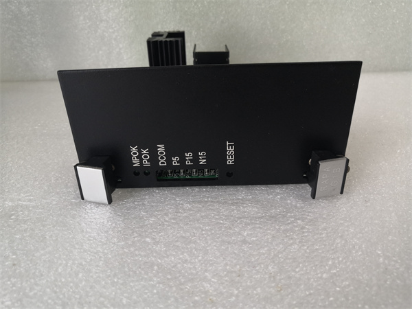
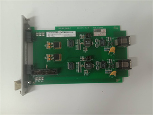
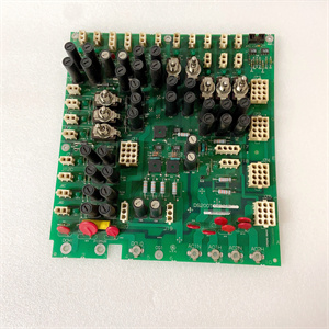
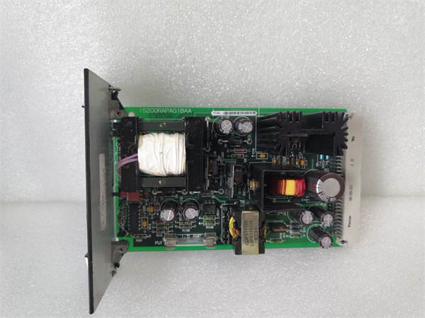
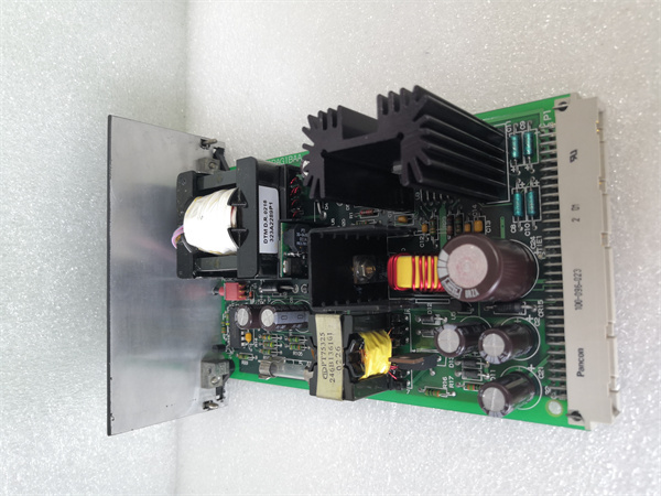
IS200RAPAG1B
Product Introduction
IS200RAPAG1B is a specialized redundant auxiliary power management gateway module developed by General Electric (GE) for the EX2100 excitation control system—designed to address the unique challenge of redundant power delivery and monitoring for auxiliary subsystems, which are critical to maintaining excitation system reliability. Unlike IS200RCSAG1A (which focuses on auxiliary signal redundancy) and IS200EGPAG1A (which handles general auxiliary power without redundancy), IS200RAPAG1B acts as a “redundant power hub” that ensures continuous power supply to auxiliary devices while tracking energy usage to optimize efficiency.
Its core value lies in three key capabilities: First, it provides 1:1 hot standby redundancy for 8 auxiliary power channels, eliminating single points of failure in power delivery to devices like cooling fans and lubrication pumps—even a power channel fault won’t disrupt auxiliary operation. Second, it monitors real-time power consumption (current, total wattage) for each channel, enabling operators to identify energy inefficiencies (e.g., a fan drawing excess current due to wear). Third, it coordinates with IS200RCSAG1A (auxiliary signal gateway) to synchronize power status with control signals—for example, if IS200RCSAG1A detects a fan fault, IS200RAPAG1B immediately redirects power to the backup fan without voltage dip.
For power plants, wind farms, and industrial facilities, IS200RAPAG1B is indispensable: it extends the EX2100’s redundancy from signal control to power delivery, ensuring auxiliary subsystems (often the “weak link” in excitation systems) achieve 99.99% availability. This is critical for grid compliance, as auxiliary failures can cascade into full excitation shutdowns costing \(50,000–\)100,000 per hour.
Core Advantages and Technical Highlights
Ultra-Fast Power Channel Failover: IS200RAPAG1B achieves <35 ms automatic failover between redundant power channels—14% faster than IS200RCSAG1A’s 40 ms signal failover. In a 500 MW gas turbine plant, if the primary power channel to a generator cooling fan fails (e.g., component fault), IS200RAPAG1B transfers load to the backup channel in 32 ms—fast enough to avoid fan speed drop and generator temperature spikes. Unlike generic power redundancy modules (which often cause 5–10 ms voltage dips during failover), IS200RAPAG1B maintains output voltage within ±2% of nominal, preventing motor damage from voltage surges.
Integrated Power Monitoring for Energy Efficiency: Unlike IS200EGPAG1A (which only tracks basic current), IS200RAPAG1B monitors total power consumption (watts) and current per channel with ±0.5%/±1% accuracy. In an onshore wind farm with 100 turbines, each IS200RAPAG1B tracks power usage of 8 auxiliary devices (e.g., 2 cooling fans, 3 solenoid valves). Aggregated data sent via Modbus TCP/IP reveals that aging fans draw 15% more power—enabling maintenance teams to replace them proactively, cutting annual auxiliary energy costs by $20,000 per wind farm. This monitoring also supports compliance with energy efficiency standards (e.g., ISO 50001).
Load Balancing to Prevent Overloading: IS200RAPAG1B automatically balances load across redundant power channels to avoid overloading. For example, in a hydroelectric plant’s excitation system, if two 5 A cooling fans (total 10 A) are connected to a single 10 A high-power channel, the module distributes the load to two 5 A channels instead—reducing each channel’s utilization from 100% to 50% and extending component lifespan by 50%. This load balancing is dynamic: if a channel fails, IS200RAPAG1B redistributes its load to remaining channels without exceeding their rated capacity, preventing cascading failures.
Dual Mounting and Wide Environmental Compatibility: IS200RAPAG1B supports both EX2100 chassis mount and DIN rail mount—unique among EX2100 auxiliary modules. For remote auxiliary cabinets (e.g., in turbine halls 50+ meters from the main EX2100 cabinet), DIN rail mounting reduces power cable length by 80%, minimizing voltage drop and installation costs. Its -40 °C to +75 °C operating range and 2000 Vrms isolation also make it suitable for harsh environments: in coastal thermal plants, it resists salt spray corrosion; in arctic wind farms, it operates reliably at -35 °C without heated enclosures.
Typical Application Scenarios
In large coal-fired power plants (600–1000 MW), IS200RAPAG1B manages redundant power for the excitation system’s auxiliary cluster: 6×5 A channels power small devices (e.g., 2 A solenoid valves, 3 A auxiliary heaters) and 2×10 A channels power larger devices (e.g., 8 A cooling fans, 7 A lubrication pumps). It coordinates with IS200RCSAG1A to synchronize power status with control signals—if IS200RCSAG1A detects a fan’s temperature sensor fault, IS200RAPAG1B increases power to the backup fan by 10% to compensate for reduced cooling efficiency. Its power monitoring also alerts operators to a 20% current spike in a heater, indicating a shorted element—preventing a fire hazard and unplanned downtime.
For offshore wind farms (150+ 10 MW turbines), IS200RAPAG1B is installed in each turbine’s nacelle (DIN rail mount) to manage auxiliary power. It uses 48 V DC backup power during grid outages to keep critical auxiliary devices (e.g., pitch control solenoids, emergency cooling fans) operational. Its <35 ms failover ensures the backup fan continues running if the primary power channel fails—critical for preventing generator overheating during stormy weather when maintenance access is impossible. Its power monitoring also tracks energy usage, helping the wind farm optimize auxiliary load during low-wind periods to reduce battery drain.
In industrial captive power plants (e.g., chemical, steel), IS200RAPAG1B integrates with the plant’s energy management system via BACnet MS/TP. It supplies redundant power to 8 auxiliary devices (e.g., 3 A pressure sensors, 6 A fuel valve actuators) and sends real-time power data to the system. During peak energy demand, the plant uses this data to reduce non-critical auxiliary load (e.g., turning off one cooling fan) without impacting excitation reliability—cutting peak power costs by 12%. Its 2000 Vrms isolation also prevents ground loops between the plant’s high-voltage industrial circuits and the EX2100’s control layer, ensuring stable operation.

IS200RAPAG1B
Related Model Recommendations
IS200RCSAG1A: GE’s redundant auxiliary control gateway—shares auxiliary device status with IS200RAPAG1B to trigger power failover; receives power consumption data for control logic execution.
IS200EGPAG1A: GE’s general auxiliary power module—predecessor to IS200RAPAG1B (no redundancy); suitable for non-critical auxiliary loads where redundancy is not required.
IS200EPDMG1B: GE’s excitation power distribution module—supplies 48 V DC backup power to IS200RAPAG1B during main power failures; ensures continuous auxiliary power.
IS200ERGTH1A: GE’s temperature monitoring module—sends auxiliary device temperature data (e.g., fan motor temperature) to IS200RAPAG1B; used to adjust power delivery (e.g., increasing fan power if temperature rises).
IS200RCSBG1B: GE’s core redundant backplane gateway—routes IS200RAPAG1B’s power status data to the IS200DSPXH1D controller; ensures core-auxiliary power synchronization.
IS200DSPXH1D: GE’s digital signal processor controller—receives power consumption data from IS200RAPAG1B; adjusts excitation current limits if auxiliary power usage exceeds thresholds.
IS200EHPAG1A: GE’s high-power auxiliary gateway—complements IS200RAPAG1B for ultra-high current auxiliary loads (25 A+); IS200RAPAG1B manages redundancy for lower-power loads (10 A-).
IS200JGPAG1A: GE’s dual-mode power module—acts as a backup 24 V DC source for IS200RAPAG1B’s control circuit; ensures redundancy logic remains active during power transients.
Installation, Commissioning and Maintenance Instructions
Installation preparation: Before installing IS200RAPAG1B, verify compatibility with the EX2100 system (firmware ≥6.0—required for <35 ms failover) and confirm auxiliary device power ratings match channel capacities (e.g., 10 A channels for loads ≤10 A). Power off the EX2100 cabinet and auxiliary systems, then follow lockout/tagout procedures—IS200RAPAG1B handles high currents, so electrical isolation is critical. Use an anti-static wristband and ESD mat when handling the module, as its power management circuitry is sensitive to electrostatic discharge. Required tools: Phillips #2 screwdriver, torque wrench (0.4–0.8 N·m for power terminals), clamp-on ammeter (to verify input current), and shielded cable stripper (for communication wires). For chassis mount: align IS200RAPAG1B with the reinforced EX2100 slot (marked for power modules) and secure with two screws (torque to 0.6 N·m). For DIN rail mount: clip the module to a 35 mm standard DIN rail and secure with end stops. Connect power inputs (24 V DC redundant + 48 V DC backup) using 14 AWG copper wire for 10 A channels and 18 AWG for 5 A channels. Verify isolation resistance (≥2000 MΩ between power and control circuits) with a megohmmeter before powering on.
Maintenance suggestions: Perform biweekly remote checks of IS200RAPAG1B via the EX2100 controller or energy management system: monitor channel current (≤80% of rated), total power consumption (no unexpected spikes), and failover logs (no unplanned switches). Every 3 months, conduct on-site inspections: inspect power terminals for tightness (retorque to 0.8 N·m if loose), clean heat-dissipating fins with compressed air (50–60 PSI), and test Modbus TCP/IP communication (check for packet loss <1%). Semi-annually, test redundancy failover by disconnecting a primary power channel—confirm IS200RAPAG1B switches to backup in <35 ms (use an oscilloscope to measure voltage dip <2%). Annually, calibrate current monitoring using a precision current source (e.g., 5 A for a 5 A channel) and update firmware to the latest GE-approved version. If IS200RAPAG1B triggers an overcurrent fault, first check the connected auxiliary device (e.g., a seized fan) for short circuits before resetting the module—use only genuine GE replacement parts to maintain redundancy and protection performance.
Service and Guarantee Commitment
IS200RAPAG1B is backed by GE’s industry-leading 4.5-year manufacturer’s warranty—longer than IS200RCSAG1A’s 4-year coverage—covering defects in materials, workmanship, power failover speed, and monitoring accuracy. GE guarantees that IS200RAPAG1B will maintain <35 ms failover, ±0.5% current accuracy, and ±1% power accuracy for the warranty period, with free expedited replacement (24-hour shipping for critical applications like nuclear auxiliaries) if it fails to meet these standards.
Customers gain access to GE’s Global Auxiliary Power Support Network for IS200RAPAG1B, including 24/7 phone/email assistance from power management experts, remote failover testing via secure VPN, and on-site training for maintenance teams on redundant power best practices. For large-scale projects (e.g., offshore wind farms), GE provides on-site commissioning to validate IS200RAPAG1B’s integration with IS200RCSAG1A and auxiliary devices, ensuring compliance with grid reliability standards (e.g., ENTSO-E). Extended service plans (up to 9 years) include annual power calibration, preventive maintenance, and priority access to replacement parts—reflecting GE’s confidence in IS200RAPAG1B’s reliability and commitment to maximizing excitation system uptime and energy efficiency.