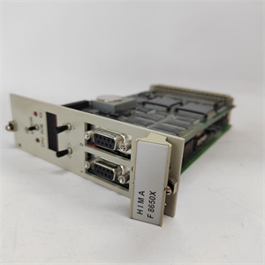
Description
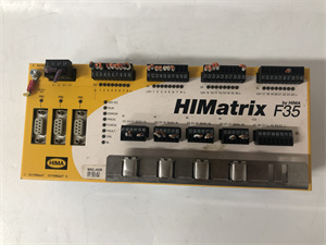
The safety-related F35 controller is a compact system located in a metal enclosure with 24
digital inputs, 8 digital outputs, 2 counters and 8 analog inputs.
The controller is available in 3 model variants for SILworX and 3 model variants for
ELOP II Factory, see Chapter 3.2. All variants are described in this manual.
The controller is equipped with safety-related digital inputs and outputs, safety-related
counters and safety-related analog inputs.
Safety-Related Digital Inputs
The controller is equipped with 24 digital inputs. The state (HIGH, LOW) of each input is
signaled by an individual LED.
The input signals are captured as analog measurements and provided to the program as a
range of INT values from 0…3000 (0…30 V). Configurable thresholds are used to generate
BOOL values, see Table 26
The default setting is:
Low level: < 7 V High level: > 13 V
The thresholds are set using system parameters taking the safety-related accuracy into
account, see Table 43 and Table 44.
For the external wiring and the connection of sensors, apply the de-energized-to-trip
principle. Thus, if a fault occurs, the input signals adopt a de-energized, safe state (low
level).
An external wire is not monitored, however, an open-circuit is considered as safe low level.
3.1.1.1 Reaction in the Event of a Fault
If the device detects a fault on a digital input, the user program processes a low level in
accordance with the de-energized to trip principle.
The device activates the FAULT LED.
In addition to the channel signal value, the user program must also consider the
corresponding error code.
The error code allows the user to configure additional fault reactions in the user program.