Description
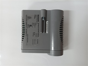
Honeywell C7012E1104 Product Description
1. Product Overview
The Honeywell C7012E1104 is a sophisticated solid – state ultraviolet (UV) flame detector, meticulously engineered to meet the exacting demands of flame detection within a diverse array of industrial and commercial combustion applications. As a key component in flame safeguard systems, it plays a pivotal role in ensuring the safe and efficient operation of burners. By precisely sensing the ultraviolet radiation emitted during the combustion process of various carbon – containing fuels, such as natural gas, LP gas, and oil, it enables prompt responses to the presence or absence of flames, thereby preventing potential hazards and optimizing combustion efficiency.
2. Detailed Parameter Table
| Parameter Name | Parameter Value |
| Product Model | C7012E1104 |
| Manufacturer | Honeywell |
| Product Category | UV Flame Detector |
| Application | Gas – fired burners, oil – fired burners, coal – fired burners |
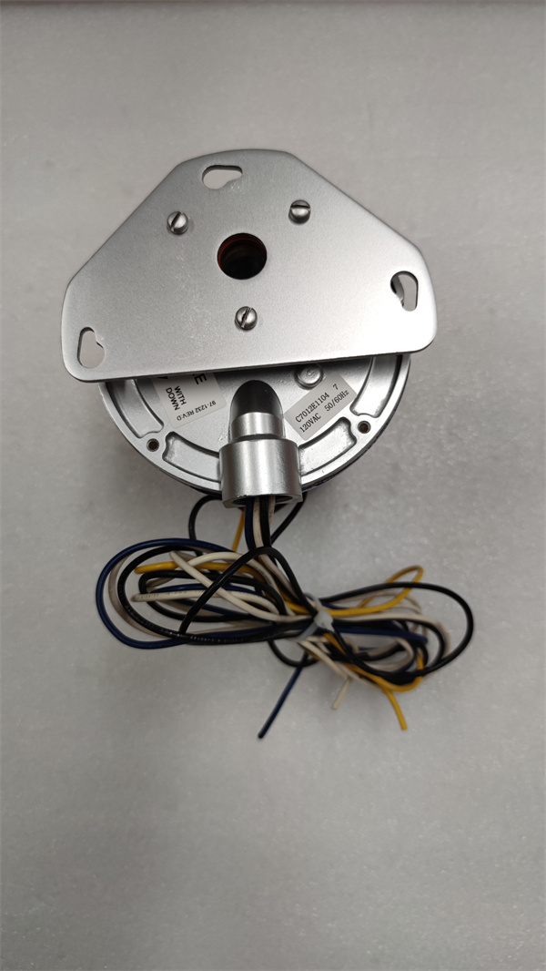
| Mounting | 3/4 in. NPT (National Pipe Thread) |
| Dimensions (inches) | 5 1/4 in. diameter (including mounting flange) x 7 7/32 in. long |
| Dimensions (millimeters) | 133 mm diameter (including mounting flange) x 183 mm long |
| Lead Length (inches) | 96 in. |
| Electrical Connections | 6 NEC Class 1 color – coded lead wires |
| Electrical Ratings | 120 VAC |
| Frequency | 50 Hz / 60 Hz |
| Power Consumption | 7.0 W |
| Ambient Temperature Range (°F) | – 20°F to + 175°F |
| Ambient Temperature Range (°C) | – 29°C to + 79°C |
| Protection Class | Meets NEMA 4 standards with viewing window rated to 20 psi |
| Weight (approx.) | 4.25 lb (1.9 kg) |
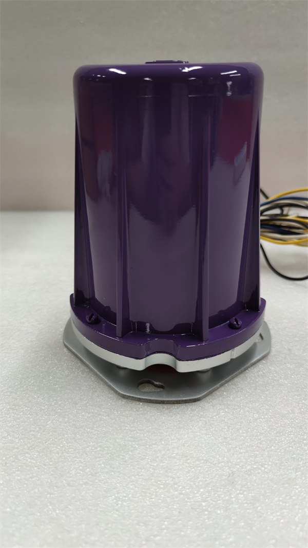
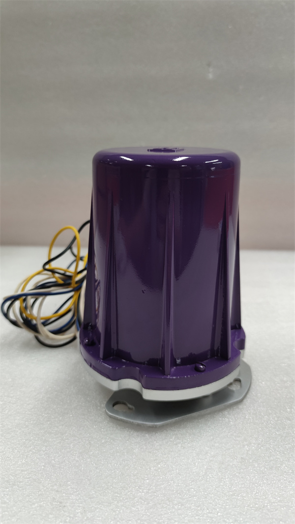
| Included Components | Cast case and cover |
| Compatible with Flame Amplifiers | R7247C, R7847C |
Honeywell C7012E1104
3. Product Introduction
This self – checking UV flame detector, often referred to as the “Purple Peeper,” is designed with user – friendliness and reliability in mind. Its solid – state electronic circuitry not only ensures low power consumption but also significantly enhances its reliability compared to previous models that utilized vacuum electron tube circuitry. The C7012E1104 can be mounted horizontally, vertically, or at any angle in – between, providing flexibility in installation based on the specific requirements of the combustion system.
The detector features a field – replaceable ultraviolet radiation sensing tube and a quartz viewing window. This design allows for easy maintenance and replacement of key components in the field, reducing downtime and maintenance costs. The threaded conduit fitting and color – coded lead wires enable rapid and error – free electrical installation, streamlining the setup process for technicians.
4. Core Advantages and Technical Highlights
4.1 Dynamic Self – Checking Functionality
The C7012E1104 is equipped with a dynamic self – checking mechanism. This feature continuously monitors the integrity of the detector’s internal components and its flame – sensing capabilities. In the event of a malfunction or a deviation from normal operating conditions, the self – checking function can quickly identify the issue and trigger appropriate actions, such as sending an alarm signal to the control system. This proactive approach to self – diagnosis significantly enhances the overall reliability and safety of the flame detection system, reducing the risk of undetected failures.
4.2 High – Sensitivity UV Sensing
The detector’s ultraviolet radiation sensing tube is highly sensitive to the UV radiation emitted by flames. It can accurately detect even the faintest of flames, ensuring that the burner system can respond promptly to changes in the combustion state. Whether it’s a small pilot flame igniting a large – scale main burner or monitoring the continuous combustion process, the C7012E1104 can precisely identify the presence of the flame and transmit the corresponding signal to the associated flame amplifiers (such as R7247C and R7847C), enabling seamless control of the burner operation.
4.3 Versatile Mounting Options
With its 3/4 in. NPT mounting, the C7012E1104 offers versatile mounting possibilities. It can be easily integrated into existing burner setups, whether in new installations or retrofitting projects. The ability to mount the detector at various angles allows for optimal positioning to achieve the best line – of – sight to the flame, maximizing its detection accuracy. This flexibility is particularly useful in complex combustion systems where the location and orientation of the flame may vary.
4.4 Quick and Easy Electrical Installation
The threaded conduit fitting and 6 NEC Class 1 color – coded lead wires simplify the electrical hookup process. Technicians can quickly and securely connect the detector to the control system, minimizing installation time and reducing the likelihood of wiring errors. The color – coding of the wires provides clear guidance for proper connection, ensuring that the electrical installation is both efficient and reliable.
4.5 Reduced Nuisance Shutdowns
In applications where sighting the flame may be challenging or subject to interference, wiring two C7012E1104 detectors in parallel can effectively reduce nuisance shutdowns. This parallel wiring configuration allows for a more robust and reliable flame detection system. If one detector experiences a false signal or temporary interference, the other detector can still accurately detect the flame, preventing unnecessary shutdowns of the burner system. This feature is especially valuable in industrial environments where continuous operation is crucial for productivity and efficiency.
4.6 Robust Construction and Protection
The C7012E1104 is housed in a cast case and cover, providing excellent protection against mechanical impacts and environmental factors. Meeting NEMA 4 standards with a viewing window rated to 20 psi, it can withstand exposure to dust, water splashing, and moderate pressure. This robust construction ensures that the detector can operate reliably in harsh industrial and commercial environments, where it may be exposed to vibrations, moisture, and other contaminants.
5. Typical Application Scenarios
5.1 Industrial Furnaces
In industrial furnaces used in industries such as metalworking, glass manufacturing, and ceramic production, the C7012E1104 is an essential component for flame monitoring. These furnaces operate at high temperatures and require precise control of the combustion process to ensure product quality. The detector accurately senses the flames, allowing for real – time adjustments to the fuel and air supply. By maintaining stable combustion, it helps to optimize energy consumption, reduce emissions, and prevent costly disruptions to the production process. For example, in a glass – blowing furnace, the C7012E1104 ensures that the flames provide consistent heat for shaping the glass, resulting in high – quality products.
5.2 Power Generation Plants
Power generation plants that use gas – fired, oil – fired, or coal – fired boilers rely on the C7012E1104 to ensure the safe and efficient operation of their combustion systems. The detector monitors the flames in the burners, providing crucial feedback to the control system. In the event of a flame failure or an abnormal combustion condition, it can quickly trigger alarms and initiate safety shutdown procedures. This helps to prevent unburned fuel from accumulating in the boiler, which could lead to explosions or other dangerous situations. By maintaining stable combustion, the C7012E1104 contributes to the reliable generation of electricity, minimizing downtime and ensuring a stable power supply.
5.3 Commercial Heating Systems
Commercial buildings, such as hotels, hospitals, and office buildings, often use gas – fired or oil – fired heating systems. The C7012E1104 is used to monitor the flames in the burners of these heating systems, ensuring safe and efficient operation. It can detect any signs of misfires, incomplete combustion, or flame instability. In case of abnormal conditions, the detector can trigger alarms and shut down the heating system to protect the building and its occupants from potential hazards. For instance, in a hotel’s central heating system, the C7012E1104 helps to maintain a comfortable indoor temperature while ensuring the safety of guests and staff.
Honeywell C7012E1104
6. Installation, Commissioning and Maintenance Instructions
6.1 Installation Preparation
Select an appropriate location on the combustion system with a clear line – of – sight to the flame for mounting the C7012E1104. Ensure that the location is free from obstructions and is within the specified ambient temperature range.
Check the integrity of the detector and all its components, including the sensing tube, quartz viewing window, cast case, and cover, before installation.
Prepare the 6 NEC Class 1 color – coded lead wires for connection to the detector and the associated flame amplifiers or control system. Use wires of the appropriate gauge to handle the electrical current.
Ensure that the installation area is clean and free from dust, debris, and moisture to prevent interference with the detector’s operation.
6.2 Commissioning
Mount the C7012E1104 on the 3/4 in. NPT connection point using appropriate tools. Tighten the connection securely to ensure a stable and accurate alignment with the flame.
Connect the 6 color – coded lead wires to the detector according to the wiring diagram provided in the product manual. Make sure the connections are tight and properly insulated to prevent electrical shorts.
Power on the burner system and the associated control system. Observe the detector’s response to the presence of the flame. The detector should quickly detect the flame and transmit a signal to the control system.
Use a calibration tool, if available, to verify the accuracy of the detector’s flame detection. Adjust the calibration settings if necessary to ensure optimal performance. Check the dynamic self – checking function by simulating a minor fault condition (following the manufacturer’s guidelines) to ensure that the self – checking mechanism works as expected.
6.3 Maintenance
Regularly inspect the C7012E1104 for any signs of physical damage, such as cracks in the cast case, damage to the sensing tube or quartz viewing window, or corrosion on the electrical connections. If any damage is detected, replace the affected components immediately.
Clean the detector’s surface and the quartz viewing window periodically to remove any dust, dirt, or contaminants that may have accumulated. Use a soft, dry cloth or a mild cleaning solution to clean the components, taking care not to damage the sensing tube or other sensitive parts.
Check the integrity of the electrical connections regularly. Ensure that the wires are not frayed, loose, or corroded. If any issues are found, repair or replace the wires as needed.
Monitor the detector’s performance over time. If there are any signs of reduced sensitivity, false alarms, or inaccurate flame detection, consider replacing the sensing tube. Since the sensing tube is field – replaceable, trained technicians can quickly and easily swap it out to restore the detector’s optimal performance.
Periodically review the product manual and any updates or bulletins issued by Honeywell to stay informed about any recommended maintenance procedures or product improvements.
7. Service and Guarantee Commitment
While specific warranty details may vary, Honeywell is committed to providing reliable after – sales support for the C7012E1104. In the event of a manufacturing defect, Honeywell’s dedicated technical support team is available to offer prompt assistance. They can help with troubleshooting, and if necessary, arrange for the repair or replacement of the detector, subject to the terms and conditions of the applicable warranty.
Customers can access comprehensive installation and operation manuals on Honeywell’s official website. These manuals offer detailed, step – by – step instructions for installation, commissioning, and maintenance of the C7012E1104. Additionally, Honeywell may offer training programs for customers who want to enhance their understanding of the proper use and integration of this UV flame detector in combustion applications. This support ensures that customers can maximize the performance and lifespan of the C7012E1104, while maintaining the highest standards of safety and efficiency in their burner systems.