Description
System Architecture & Operational Principle
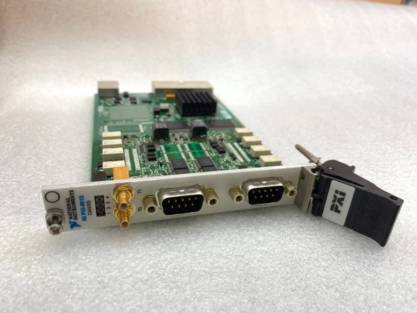
The NI PXI-8513 780688-02 is a 2-port software-selectable PXI CAN interface module designed for Level 1 (Device) or Level 2 (Control) of the Purdue Model in industrial automation and test systems. It resides in a PXI chassis (3U form factor) and serves as the bridge between PXI controllers (e.g., NI PXI-8106) and external CAN devices (e.g., automotive ECUs, industrial robots).
Upstream Communication
Receives control signals from a PXI controller via the PXI bus. These signals include:
-
CAN Frame Commands: Which messages to send/receive (e.g., “read sensor data”);
-
Timing Triggers: Synchronization with other devices (e.g., start a measurement after a CAN message is received).
Downstream Communication
Transmits CAN messages to external devices via two 9-pin D-SUB connectors (one per port). The module uses software-selectable transceivers to support multiple CAN physical layers:
-
High-Speed/FD: For fast communication (up to 5 Mbps);
-
Low-Speed/Fault-Tolerant: For reliable communication in noisy environments;
-
Single-Wire: For cost-effective applications.
Operational Advantages
-
High Flexibility: Software-selectable physical layers eliminate the need for multiple modules (e.g., one module for high-speed, another for low-speed);
-
Precise Timing: 1 µs timestamp resolution enables accurate synchronization with external devices;
-
Low Latency: NI-XNET driver with device-driven DMA engine minimizes CPU overhead, allowing real-time processing of hundreds of CAN frames per second.

NI PXI-8513
Core Technical Specifications
|
Attribute
|
Specification
|
|---|---|
|
Ports
|
2 independent CAN ports (9-pin D-SUB connectors)
|
|
Physical Layers
|
Software-selectable: High-Speed/FD, Low-Speed/Fault-Tolerant, Single-Wire
|
|
Transceivers
|
Onboard (TJA1041/TJA1043, TJA1054A/TJA1055T, AU5790/NCV7356) or external
|
|
Timestamp Resolution
|
1 µs (microsecond)
|
|
Baud Rate
|
Up to 5 Mbps (High-Speed/FD); up to 125 kbps (Low-Speed)
|
|
Driver Support
|
NI-XNET (compatible with LabVIEW, C/C++, LabWindows/CVI)
|
|
Trigger Interfaces
|
7 I/O trigger lines (PXI/RTSI) for synchronization
|
|
Operating Temperature
|
0°C to +55°C (32°F to 131°F)
|
|
Storage Temperature
|
-20°C to +70°C (-4°F to 158°F)
|
|
Dimensions (W×H×D)
|
~160 mm × 100 mm × 20 mm (6.3 in × 3.9 in × 0.8 in) (3U PXI module)
|
|
Weight
|
~0.5 kg (1.1 lbs)
|
|
Certifications
|
CE, UL, CSA, RoHS
|
Customer Value & Operational Benefits
Enhanced Test Efficiency
The PXI-8513’s 2 ports allow simultaneous communication with multiple CAN devices, reducing test time by up to 50%. For example, an automotive test system using the module can test 2 ECUs at once, compared to testing them sequentially with a single-port module.
Improved Compatibility
Software-selectable physical layers eliminate the need for custom hardware modifications, making the module compatible with a wide range of devices (e.g., legacy industrial controllers, modern automotive ECUs). A manufacturing engineer reported a 30% reduction in integration time after switching to the PXI-8513.
Reduced Downtime
The module’s hot-swappable design allows replacement without shutting down the PXI chassis, minimizing downtime during maintenance. A field engineer noted that the PXI-8513’s hot-swap feature reduced maintenance downtime from 2 hours to 15 minutes per incident.
Cost-Effective Scalability
Adding more PXI-8513 modules to a chassis allows scaling up the number of CAN ports, eliminating the need for expensive external CAN hubs. A research lab using 4 PXI-8513 modules (8 ports) saved $5,000 compared to using external hubs.
Field Engineer’s Notes (From the Trenches)
When configuring the PXI-8513, always verify the physical layer selection—using the wrong layer (e.g., High-Speed for a Low-Speed device) can cause communication errors. I once saw a site where a technician used High-Speed for a legacy sensor, resulting in a 100% packet loss. Switching to Low-Speed/Fault-Tolerant fixed the issue immediately.Another gotcha: use shielded twisted-pair (STP) cables for the CAN connections—unshielded cables can pick up electromagnetic interference (EMI) from nearby power lines, leading to signal degradation. A factory using unshielded cables reported a 20% error rate in CAN messages; switching to STP cables eliminated the problem.If the module’s “FAULT” LED is red, check the transceiver—the onboard transceiver may be damaged (e.g., from a voltage spike). Use a multimeter to test the transceiver’s power supply (should be 5V DC) and replace the module if necessary.NI PXI-8513
Real-World Applications
-
Automotive ECU TestingThe PXI-8513 is used to test engine control units (ECUs) in automotive manufacturing. It communicates with the ECU via CAN to read sensor data (e.g., engine temperature, fuel level) and send commands (e.g., “adjust fuel injection”). The 1 µs timestamp resolution ensures accurate synchronization with the ECU’s internal clock.
-
Industrial Robot ControlIn industrial automation, the PXI-8513 is used to control robotic arms via CAN. It sends position commands to the robot’s controller and receives feedback (e.g., “arm reached target position”). The dual ports allow simultaneous control of two robots, increasing throughput.
-
Aerospace Avionics TestingAerospace manufacturers use the PXI-8513 to test avionics systems (e.g., flight control computers) via CAN. It simulates sensor inputs (e.g., altitude, airspeed) and verifies the avionics’ responses. The software-selectable physical layers allow testing of both legacy (Low-Speed) and modern (High-Speed/FD) avionics.
High-Frequency Troubleshooting FAQ
Q: What does the “FAULT” LED indicate on the NI PXI-8513 780688-02?
A: The red “FAULT” LED indicates a critical error, such as:
-
Transceiver Failure: The onboard transceiver is damaged (check the power supply with a multimeter);
-
Baud Rate Mismatch: The module’s baud rate does not match the external device (verify the baud rate in NI MAX);
-
Cable Issue: The CAN cable is disconnected or damaged (check the cable with a multimeter).
Q: Can the NI PXI-8513 780688-02 be used with PXIe systems?
A: Yes, the PXI-8513 is compatible with PXI Express hybrid slots (as long as the chassis supports 3U PXI modules). For native PXIe systems, use the NI PXIe-8513 module.
Q: How do I configure the NI PXI-8513 780688-02 for High-Speed/FD communication?
A: Follow these steps:
-
Open NI MAX: Launch Measurement & Automation Explorer (NI MAX);
-
Select the Module: Expand “Devices and Interfaces” and select the PXI-8513;
-
Choose Physical Layer: Under “CAN Physical Layer,” select “High-Speed/FD”;
-
Set Baud Rate: Enter the desired baud rate (e.g., 5 Mbps);
-
Test Communication: Use NI-XNET to send a test message and verify the response.
Q: Why is the NI PXI-8513 780688-02 not communicating with the external device?
A: Check three things first:
-
Physical Layer: Ensure the module’s physical layer matches the external device (e.g., High-Speed for a High-Speed device);
-
Baud Rate: Verify the baud rate is the same on both the module and the external device;
-
Cable: Ensure the CAN cable is connected correctly (no loose connections) and is shielded.
Commercial Availability & Pricing
Please note: The listed price is not the actual final price. It is for reference only and is subject to appropriate negotiation based on current market conditions, quantity, and availability.