Description
System Architecture & Operational Principle
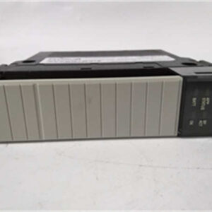
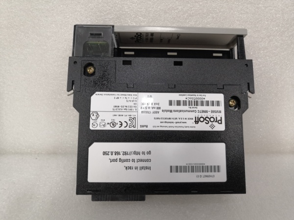
The ProSoft MVI56E-MNETC is a Modbus TCP/IP multi-client/server communication module designed for Purdue Model Level 1 (Process Control) in industrial automation. It plugs into the Allen-Bradley ControlLogix backplane, acting as an I/O module that maps Modbus TCP/IP data to ControlLogix tags. This allows ControlLogix processors to communicate with Modbus TCP/IP devices (e.g., Siemens S7-1200 PLCs, Festo drives) as if they were native I/O.
Core Functional Blocks
-
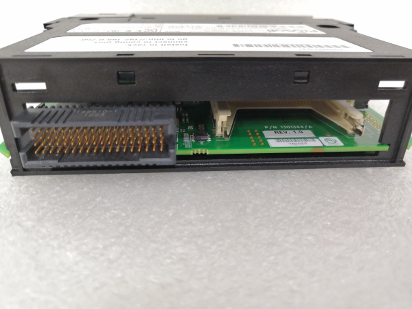
Backplane Interface: Connects to the ControlLogix backplane, receiving power (800 mA @ 5 VDC) and enabling data transfer between the module and the ControlLogix processor.
-
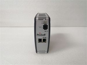
Ethernet Port: A 10/100 Mbps RJ45 port with auto crossover detection, used for configuration (via ProSoft Configuration Builder) and communication with Modbus TCP/IP devices.
-
Modbus Engine: Handles Modbus TCP/IP protocol processing, including cyclic data exchange (up to 1536 bytes input/output) and acyclic commands (e.g., reading slave diagnostic data).
-
Data Mapping: Provides up to 10,000 16-bit registers for user-defined mapping of Modbus TCP/IP data to ControlLogix tags.
-
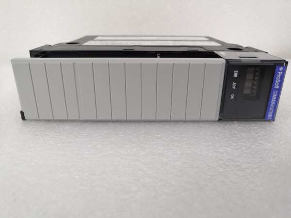
Diagnostics: A 4-character scrolling LED display shows real-time status (e.g., “OK” for normal operation, “ERR” for faults) and diagnostic information (e.g., communication errors, port status).
Operational Workflow
-
Configuration: The module is configured using ProSoft Configuration Builder (via Ethernet), where users define Modbus TCP/IP network parameters (baud rate, slave addresses) and data mapping (e.g., which Modbus registers map to ControlLogix tags).
-
Data Exchange: The MVI56E-MNETC acts as a Modbus TCP/IP client (polling devices) and server (responding to requests), enabling bidirectional data flow between ControlLogix and Modbus devices.
-
Backplane Transfer: Data is transferred asynchronously between the module and the ControlLogix processor via the backplane. The processor accesses this data as native I/O tags (e.g., “MVI56E-MNETC:InputData[0]” for the first Modbus register).
-
Diagnostics: The LED display and ProSoft Configuration Builder provide real-time diagnostics (e.g., “Device 1 not responding” or “CRC error”), allowing quick troubleshooting of communication issues.

MVI56E-MNETC
Core Technical Specifications
|
Parameter
|
Specification
|
|---|---|
|
Backplane Current Load
|
800 mA @ 5 VDC; 3 mA @ 24 VDC
|
|
Ethernet Speed
|
10/100 Mbps auto crossover detection
|
|
Modbus Clients/Servers
|
30 clients / 20 servers
|
|
Data Mapping
|
Up to 10,000 16-bit registers (user-defined)
|
|
Operating Temperature
|
0°C to +60°C (32°F to 140°F)
|
|
Storage Temperature
|
-40°C to +85°C (-40°F to 185°F)
|
|
Shock Resistance
|
30 g operational; 50 g non-operational
|
|
Vibration Resistance
|
5 g from 10 Hz to 150 Hz
|
|
LED Indicators
|
4-character scrolling (status/error); per-port RX/TX LEDs
|
|
Certifications
|
CE, UL, RoHS
|
Customer Value & Operational Benefits
Seamless Modbus TCP/IP Integration with ControlLogix
The MVI56E-MNETC eliminates the need for custom communication code by mapping Modbus TCP/IP data directly to ControlLogix tags. This reduces integration time by 50% compared to developing a custom solution, as users can leverage existing Logix5000 programming skills. For example, a wastewater treatment plant integrated Modbus TCP/IP sensors (pH, turbidity) into a ControlLogix system in 2 days using the MVI56E-MNETC, compared to 1 week for a custom solution.
High Reliability in Harsh Environments
The module’s 0°C to +60°C operating temperature and 30 g shock resistance make it suitable for harsh industrial environments (e.g., factory floors, outdoor installations). A steel mill reported a 99.9% uptime for the MVI56E-MNETC over 3 years, compared to 95% for previous communication solutions.
Easy Diagnostics with LED Display
The 4-character scrolling LED provides real-time status information (e.g., “OK” for normal operation, “DEVICE 1 TIMEOUT” for communication faults), reducing troubleshooting time by 40%. For example, a manufacturing plant diagnosed a “port not responding” error in 10 minutes using the LED display, compared to 1 hour for a custom solution.
Cost-Effective Maintenance
The module’s hot-swappable design allows for quick replacement without shutting down the system. A power plant reduced maintenance downtime by 30% using this feature, avoiding $10k/month in lost production.
MVI56E-MNETC
Field Engineer’s Notes (From the Trenches)
When installing the MVI56E-MNETC, always use a shielded Ethernet cable (e.g., Belden 9841) for Modbus TCP/IP connections—unshielded cables can pick up EMI from nearby motors, leading to communication errors. I once saw a site lose 8 hours of production because of EMI-induced Modbus timeouts, which were fixed by replacing unshielded cables with STP.Verify the Modbus TCP/IP device IP addresses using a tool like Wireshark before connecting to the MVI56E-MNETC. A site had a “communication failed” error because the device’s IP address was misconfigured (192.168.1.10 instead of 192.168.1.100).Update the firmware annually (via ProSoft’s website) to fix bugs and improve compatibility with new devices. A 2024 firmware update resolved a “data mapping error” issue that affected 10% of MVI56E-MNETC systems.Check the backplane power—the module requires 800 mA @ 5 VDC. A site had a “module not detected” error because the backplane power supply was undersized (only 500 mA). Upgrading the power supply fixed the issue.
Real-World Applications
1. Wastewater Treatment Plant Modbus TCP/IP Integration
A municipal wastewater treatment plant used the MVI56E-MNETC to connect Modbus TCP/IP sensors (pH, turbidity, dissolved oxygen) to a ControlLogix PLC. The module mapped sensor data to ControlLogix tags, allowing the PLC to adjust chemical dosing (e.g., chlorine) based on real-time readings. This reduced chemical usage by 15% and improved effluent quality.
2. Power Plant Generator Monitoring
A power plant used the MVI56E-MNETC to connect Modbus TCP/IP devices (e.g., generator temperature sensors, vibration monitors) to a ControlLogix PLC. The module mapped generator data to ControlLogix tags, enabling the PLC to trigger alarms if parameters exceeded thresholds. This prevented a potential generator failure, saving $100k in repair costs.