Description
System Architecture & Operational Principle
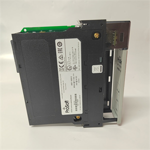
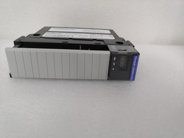
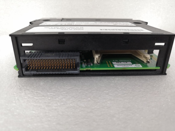
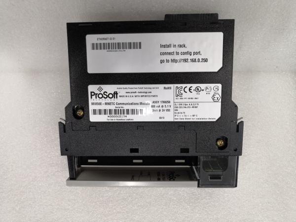
The ProSoft MVI56E-MNETC is a critical communication bridge in industrial automation systems, residing in a single slot of an Allen-Bradley ControlLogix chassis. It connects the PLC to Modbus TCP/IP networks, acting as either a client (master) to poll data from Modbus devices (e.g., VFDs, energy meters) or a server (slave) to share ControlLogix data with SCADA systems.
Upstream, the ControlLogix processor sends configuration commands and requests data via the chassis backplane. The module translates these into Modbus TCP/IP messages, transmitting them over a 10/100 Mbps Ethernet link. Downstream, it receives responses from Modbus devices (e.g., VFD speed feedback) or sends commands (e.g., setpoint adjustments) to field devices.
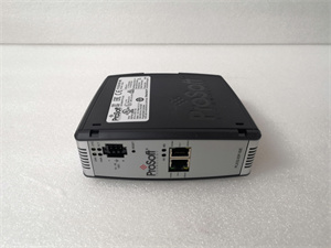
The module integrates with RSLogix 5000/Studio 5000 using a supplied Add-On Instruction (AOI), which maps Modbus data to ControlLogix tags for seamless data exchange. Its single-slot design minimizes chassis space usage, while CIPconnect technology enables remote configuration and diagnostics over EtherNet/IP or ControlNet—eliminating the need for additional gateways.
The inherent advantage lies in its ability to bridge Rockwell’s proprietary ControlLogix ecosystem with the widely adopted Modbus TCP/IP protocol, ensuring interoperability with third-party devices without compromising system performance. Hot-swappable capability allows for module replacement without shutting down the PLC, reducing downtime during maintenance.

PROSOFT MVI56E-MNETC
Core Technical Specifications
-
Backplane Compatibility: Single-slot 1756 ControlLogix chassis (supports local/remote rack installation)
-
Ethernet Port: 10/100 Base-T, RJ45 connector (CAT5 cable), auto crossover detection
-
Modbus Modes: Simultaneous client (master) and server (slave) support
-
Client Connections: Up to 30 (16 commands per client, total 480 commands)
-
Server Connections: Up to 20 (for SCADA/DCS data access)
-
Data Registers: 10,000-word capacity (user-definable mapping for input/output)
-
Backplane Current Draw: 800 mA @ 5 V DC, 3 mA @ 24 V DC
-
Operating Temperature: 0°C to 60°C (32°F to 140°F)
-
Storage Temperature: -40°C to 85°C (-40°F to 185°F)
-
Shock Resistance: 30 g operational, 50 g non-operational
-
Vibration Resistance: 5 g from 10 Hz to 150 Hz
-
Relative Humidity: 5% to 95% (non-condensing)
-
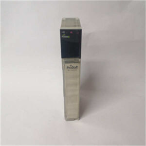
LED Indicators: Application Status (APP), Module Status (OK), Error (ERR)
-
Display: 4-character alphanumeric scrolling LED (shows IP address, port status, errors)
Customer Value & Operational Benefits
Reduced Downtime Through Hot-Swap Capability
The MVI56E-MNETC’s hot-swappable design allows technicians to replace a faulty module without powering down the ControlLogix chassis. This eliminates costly production stops—critical in industries like automotive manufacturing, where every minute of downtime translates to lost revenue.
Streamlined Integration with Third-Party Devices
By supporting Modbus TCP/IP (the de facto standard for industrial communication), the module eliminates the need for custom gateways or protocol converters. This reduces integration complexity and cost, while its compatibility with RSLogix 5000/Studio 5000 ensures seamless data mapping to ControlLogix tags. Technicians can quickly configure the module using ProSoft’s Configuration Builder software, cutting commissioning time by up to 50%.
Enhanced Diagnostic Visibility
The module’s 4-character LED display provides real-time status updates (e.g., “IP OK” or “ERR: COMM”), while the APP and OK LEDs indicate application and module health. For deeper diagnostics, technicians can use ProSoft’s remote configuration software to view error logs and network performance—reducing root-cause analysis time from hours to minutes. This visibility is invaluable in preventing unplanned outages caused by communication failures.
Field Engineer’s Notes (From the Trenches)
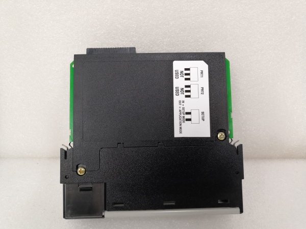
When installing the MVI56E-MNETC, always verify the ControlLogix chassis backplane power supply first. A marginal 5 V supply (below 4.9 V) can cause intermittent communication faults that mimic a bad module. Use a multimeter to measure the backplane voltage at the slot before inserting the module—this simple step saves hours of troubleshooting.Another gotcha: the module’s Ethernet port requires a straight-through CAT5 cable (not crossover) for most networks. While the module supports auto crossover detection, some industrial switches don’t play nice with it. Stick to straight-through cables unless you’ve confirmed the switch supports auto-MDI/MDIX.Finally, label the module’s IP address on the chassis—nothing’s worse than hunting for a misconfigured module in a crowded cabinet. Use a permanent marker to write the IP on the front panel; it’ll save you time during future diagnostics.PROSOFT MVI56E-MNETC
Real-World Applications
-
Automotive Parts ManufacturingA major automotive supplier uses the MVI56E-MNETC to connect a ControlLogix PLC to 24 Modbus TCP robotic arms and 12 barcode scanners. The module polls robotic position data (Modbus registers 40001-40024) and scanner serial numbers (40025-40036) every 300 ms, enabling the PLC to synchronize assembly lines and track parts. This integration reduced assembly errors by 25% and improved compliance with IATF 16949 quality standards.
-
Coal-Fired Power Plant Energy MonitoringA power plant deploys the MVI56E-MNETC to link a ControlLogix PLC with 36 Modbus TCP energy meters and 18 transformer temperature sensors. The module acts as a server, sharing real-time energy output (kWh) and temperature data with a plant-wide SCADA system. During peak demand, the SCADA system sends Modbus commands to adjust generator load—cutting energy waste by 15% and ensuring grid stability.
-
Municipal Water Treatment Pump ControlA water treatment plant uses the MVI56E-MNETC to connect a ControlLogix PLC to 12 Modbus TCP VFDs (controlling pump speed) and 8 level sensors (monitoring storage tanks). The module polls sensor data every 500 ms and sends pump speed commands to VFDs, optimizing flow based on demand. This reduced energy consumption by 20% and extended pump lifespan by 15%.
High-Frequency Troubleshooting FAQ
Q: What is the correct migration path for a ProSoft MVI56-MNET to MVI56E-MNETC?
A: The MVI56E-MNETC is a drop-in replacement for the legacy MVI56-MNET. The main differences are: (1) The MVI56E-MNETC supports simultaneous client and server modes (the MVI56-MNET was client-only); (2) The MVI56E-MNETC has a larger data register capacity (10,000 words vs. 5,000 words). To migrate, simply transfer the existing configuration from the MVI56-MNET to the MVI56E-MNETC using ProSoft’s Configuration Builder software. No changes to the ControlLogix ladder logic are required (unless you want to use the new server functionality).
Q: How do I interpret the LED status indicators on a ProSoft MVI56E-MNETC?
A: The module has three LEDs:
-
APP (Green): Solid = Application running normally; Blinking = Application initializing.
-
OK (Green): Solid = Module communicating with ControlLogix; Blinking = Module detected but not configured.
-
ERR (Red): Solid = Critical error (e.g., backplane power failure); Blinking = Non-critical error (e.g., invalid IP address).The 4-character LED display provides additional context (e.g., “IP ERR” or “COMM OK”). For a full list of codes, refer to the module’s user manual.
Q: Why am I getting “data mismatch” alarms when using the MVI56E-MNETC with a Modicon PLC?
A: This is usually caused by a configuration mismatch between the Modicon PLC’s Modbus register map and the MVI56E-MNETC’s data mapping. First, verify that the Modicon’s register addresses (e.g., 40001) match the module’s configured “Device Address” in ProSoft’s Configuration Builder. Second, check that the Modbus function codes (e.g., FC 3 for reading holding registers) are enabled in the module’s settings. Finally, ensure the Modicon PLC’s IP address is correctly entered in the MVI56E-MNETC’s client configuration.
Q: Can the MVI56E-MNETC be used in a redundant ControlLogix system?
A: Yes, the module supports redundant ControlLogix configurations (e.g., 1756-RM2). Install one MVI56E-MNETC in each redundant chassis, and configure them to mirror each other’s settings. The module’s CIPconnect technology ensures seamless failover—if one chassis fails, the other takes over communication without interrupting data flow.
Commercial Availability & Pricing
Please note: The listed price is not the actual final price. It is for reference only and is subject to appropriate negotiation based on current market conditions, quantity, and availability.