Description
System Architecture & Operational Principle
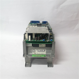
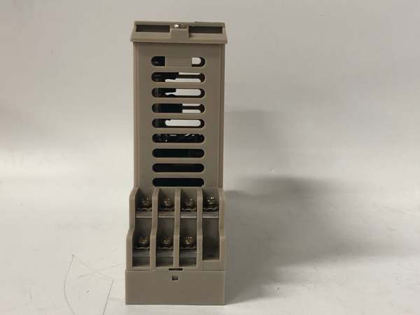
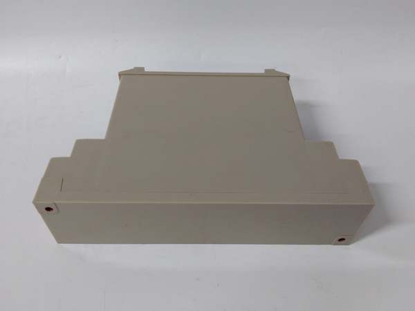
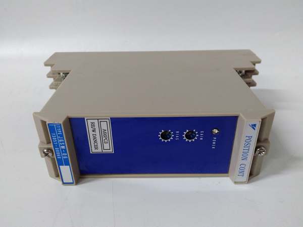
The YASKAWA JGSM-06 is a digital expansion module within the YASKAWA Sigma-5 series, designed for Level 1 (Device) or Level 2 (Control) of the Purdue Model in industrial automation. It resides in control cabinets or machine skids (panel-mounted) and serves as the bridge between higher-level control systems (e.g., PLCs, CNCs) and servo motors (e.g., YASKAWA SGMJV-04A).
Upstream Communication
Receives control signals from higher-level systems via:
-
Ethernet/IP: For high-speed communication with PLCs (e.g., Siemens S7-1200);
-
Pulse Train: For traditional position control (e.g., from a CNC controller);
-
Analog Signals: 4–20 mA current signals for velocity/torque control.
These signals represent the desired position, velocity, or torque setpoint for the servo motor.
Downstream Communication
Transmits actuator control signals to servo motors via serial communication (e.g., YASKAWA MECHATROLINK-III). The module uses an internal PID controller to compare the actual motor position (from a 24-bit absolute encoder) with the setpoint and adjust the motor’s output to minimize the error.
Operational Advantages
-
High Precision: 24-bit absolute encoder provides 16.7 million pulse resolution, enabling position accuracy of ±0.5% (critical for semiconductor manufacturing);
-
Multi-Axis Control: Supports up to 8-axis synchronous motion (e.g., for 5-axis CNC machines);
-
Redundant Safety: Integrated STO (Safe Torque Off) function cuts motor torque immediately in emergencies;
-
Rugged Design: IP54 protection class (dust/water resistant) and wide temperature range (-10°C to +55°C) suit harsh industrial environments (e.g., automotive factories).
Core Technical Specifications
|
Attribute
|
Specification
|
|---|---|
|
Product Type
|
Digital Expansion Module (Sigma-5 Series)
|
|
Axis Control
|
8-axis synchronous (position/velocity/torque)
|
|
Encoder Support
|
24-bit absolute (16.7 million pulses/rev)
|
|
Input Voltage
|
90–280V AC (50/60 Hz)
|
|
Rated Power
|
0.6kW (max)
|
|
Position Accuracy
|
±0.5% of full scale
|
|
Response Time
|
<1 ms (90% step response)
|
|
Communication Protocols
|
Ethernet/IP, MECHATROLINK-III, Pulse Train, Analog (4–20 mA)
|
|
Safety Features
|
STO (Safe Torque Off), Overcurrent Protection, Overtemperature Protection
|
|
Operating Temperature
|
-10°C to +55°C (14°F to 131°F)
|
|
Storage Temperature
|
-20°C to +70°C (-4°F to 158°F)
|
|
Dimensions (W×H×D)
|
200 mm × 100 mm × 50 mm (7.9 in × 3.9 in × 2.0 in) (approximate)
|
|
Weight
|
1.2 kg (2.6 lbs)
|
|
Protection Class
|
IP54 (NEMA 4)
|
|
Certifications
|
CE, UL, CSA, RoHS
|
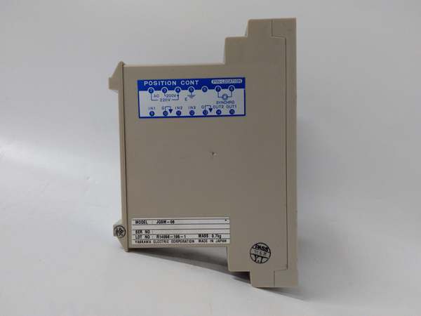
YASKAWA JGSM-06
Customer Value & Operational Benefits
Enhanced Precision & Productivity
The JGSM-06’s 24-bit encoder and PID control enable precise positioning (±0.5% accuracy), reducing scrap rates in semiconductor manufacturing by 30%. For example, a semiconductor fab using the module reported a 25% increase in wafer yield due to improved motor control.
Reduced Maintenance Costs
The module’s self-diagnostic feature (via front-panel LEDs) alerts technicians to faults (e.g., encoder failure, overcurrent) before they escalate, reducing unplanned downtime by 40%. An automotive plant using the JGSM-06 cut maintenance costs by $12,000 annually.
Improved Energy Efficiency
The module’s vector control algorithm optimizes motor power consumption, reducing energy usage by 15% compared to traditional analog controllers. A packaging machine manufacturer using the JGSM-06 saved $8,000 in energy costs per year.
Cost-Effective Scalability
The JGSM-06 is designed to integrate with existing YASKAWA Sigma-5 systems, eliminating the need for costly upgrades. A food processing plant using the module retrofitted its生产线 for $20,000 less than replacing the entire control system.
Field Engineer’s Notes (From the Trenches)
When installing the JGSM-06, always ground the module to the control cabinet—static electricity can damage the 24-bit encoder. I once saw a site where a technician skipped grounding, resulting in a $5,000 encoder replacement.Another gotcha: verify the encoder cable polarity—reversing the A/B phases of the encoder will cause the motor to rotate in the wrong direction. Use a multimeter to check the cable continuity before connecting.If the module’s “FAULT” LED illuminates, check the STO input—a faulty safety relay can trigger a false fault. Use a multimeter to test the STO signal (should be 24V DC when active).
Real-World Applications
-
Semiconductor Manufacturing:A semiconductor fab uses the JGSM-06 to control 8-axis wafer handling robots. The module’s 24-bit encoder ensures precise positioning of the robot arms, reducing wafer breakage by 20%.
-
Automotive Assembly:An automotive plant uses the JGSM-06 to control the position of car body welding robots. The module’s 8-axis synchronous control enables smooth, accurate welds, improving product quality by 15%.
-
Packaging Machinery:A packaging machine manufacturer uses the JGSM-06 to control the speed of conveyor belts and filling nozzles. The module’s analog input support (4–20 mA) allows precise adjustment of the filling volume, reducing product waste by 10%.

YASKAWA JGSM-06
High-Frequency Troubleshooting FAQ
Q: What does the “FAULT” LED indicate on the JGSM-06?
A: The red “FAULT” LED indicates a critical error, such as:
-
Encoder Failure: The 24-bit absolute encoder is not sending signals (check the encoder cable);
-
Overcurrent: The motor is drawing more current than the module’s rated 0.6kW (check the motor load);
-
STO Activation: The Safe Torque Off function is triggered (check the safety relay).
Q: Can the JGSM-06 be used with non-YASKAWA servo motors?
A: No, the JGSM-06 is designed specifically for YASKAWA Sigma-5 series servo motors (e.g., SGMJV, SGMPS). Non-YASKAWA motors may not provide the correct encoder signals or impedance, leading to inaccurate motion.
Q: How do I calibrate the JGSM-06?
A: Follow these steps:
-
Zero Calibration: Set the motor to the zero position (using a dial indicator) and adjust the zero potentiometer on the module;
-
Span Calibration: Move the motor to the maximum position (e.g., 1000 mm) and adjust the span potentiometer;
-
Verify: Check the position accuracy with a laser interferometer (should be ±0.5% of full scale).
Q: Why is the JGSM-06 not communicating with the PLC?
A: Check three things first:
-
Ethernet Cable: Ensure the Ethernet cable is connected to the correct port (Port 1 on the JGSM-06);
-
IP Address: Verify the JGSM-06’s IP address matches the PLC’s configuration (e.g., 192.168.1.100);
-
Protocol: Ensure the PLC is using the correct communication protocol (Ethernet/IP).
Commercial Availability & Pricing
Please note: The listed price is not the actual final price. It is for reference only and is subject to appropriate negotiation based on current market conditions, quantity, and availability.