Description
System Architecture & Operational Principle
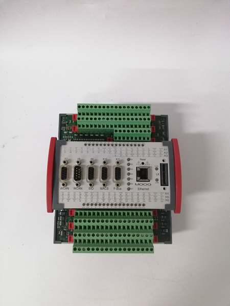
The MOOG D136-001-008 is a PLC-integrated servo valve controller designed for industrial and aerospace applications requiring high-precision motion control. It belongs to the MOOG MSC I Series, which combines a programmable logic controller (PLC) with a high-performance servo amplifier to drive hydraulic or pneumatic servo valves.
Architectural Role
The controller is positioned at Purdue Model Level 1–2 (Basic Control/Supervisory Control), acting as the interface between:
-
Upstream: PLCs (e.g., Siemens S7, Allen-Bradley ControlLogix) or HMI systems via analog inputs (±10 V) or digital signals (24 VDC).
-
Downstream: Hydraulic/pneumatic servo valves (e.g., MOOG G631/G761 series) via a 4–20 mA current output or pulse-width modulation (PWM) signals.
Its primary role is to convert PLC commands into precise valve actuator signals, maintaining tight control over flow rate, pressure, or position in dynamic systems.
Operational Principle
The D136-001-008 uses a closed-loop control algorithm to adjust the servo valve’s position based on feedback from sensors (e.g., linear potentiometers, encoders). Key operational steps include:
-
Command Reception: The PLC sends a target setpoint (e.g., “move actuator to 10 mm”) via an analog signal.
-
Signal Processing: The controller amplifies the signal and applies filtering (e.g., low-pass filter) to reduce noise.
-
Valve Actuation: The amplified signal drives the servo valve’s torque motor, adjusting the valve spool position to match the setpoint.
-
Feedback Loop: A sensor (e.g., linear encoder) measures the actual position and sends it back to the controller. The controller compares the actual position to the setpoint and adjusts the valve position until the error is minimized (typically <0.1% of full scale).
Key Architectural Advantages
-
PLC Integration: The built-in PLC allows for custom logic programming (e.g., sequential control, fault handling), reducing the need for external controllers.
-
High Bandwidth: The 2500 Hz current loop ensures fast response times (≤1 ms), critical for high-speed applications like robotics or turbine control.
-
Flexible Communication: Supports CANopen and EtherCAT protocols for integration with modern industrial networks.

MOOG D136-001-008
Core Technical Specifications
|
Parameter
|
Specification
|
|---|---|
|
Control Mode
|
Position/velocity/torque control (programmable via PLC)
|
|
Input Signals
|
±10 V analog (12-bit resolution), 24 VDC digital (dry contact/wet contact)
|
|
Output Signals
|
4–20 mA current (±80 mA overload), PWM (10 kHz–1 MHz)
|
|
Current Loop Bandwidth
|
2500 Hz (typical)
|
|
Position Feedback
|
Linear potentiometer/encoder (12-bit resolution, ±0.01 mm accuracy)
|
|
Operating Temperature
|
-40°C to +70°C (-40°F to +158°F)
|
|
Protection Rating
|
IP20 (dust-protected; suitable for control cabinets)
|
|
Power Supply
|
24 VDC (±10%; 50 W max)
|
|
Communication
|
CANopen (CiA 301/402), EtherCAT (optional)
|
|
Dimensions
|
~200 mm × 150 mm × 50 mm (7.9 in × 5.9 in × 2.0 in)
|
|
Weight
|
~1.5 kg (3.3 lbs)
|
Customer Value & Operational Benefits
1. Precision Control for Critical Applications
The D136-001-008’s 12-bit resolution and 2500 Hz current loop enable micron-level accuracy (±0.01 mm) in position control, which is essential for applications like semiconductor manufacturing (wafer alignment) or aerospace (flight control surfaces). The closed-loop feedback ensures that even small disturbances (e.g., temperature changes) do not affect performance.
2. Reduced Downtime with PLC Integration
The built-in PLC allows for custom fault-handling logic (e.g., “shut down valve if pressure exceeds 100 bar”), reducing the need for external safety relays. This integration minimizes wiring complexity and improves system reliability—critical for 24/7 operations like power generation or chemical processing.
3. Flexible Communication for Modern Networks
Support for CANopen and EtherCAT protocols allows the D136-001-008 to integrate with Industry 4.0 systems (e.g., SCADA, MES). For example, in a smart factory, the controller can send real-time valve position data to the MES, enabling predictive maintenance and process optimization.
4. Cost Savings with Compact Design
The controller’s compact size (200 mm × 150 mm × 50 mm) reduces cabinet space requirements, while the PLC integration eliminates the need for separate controllers. This cost savings is significant for small businesses or contractors who need to equip multiple machines.

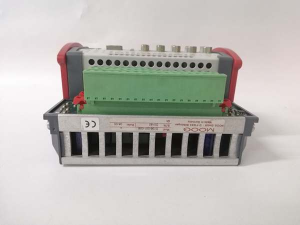
MOOG D136-001-008
Field Engineer’s Notes (From the Trenches)
When installing the D136-001-008, always use shielded twisted-pair (STP) cable for analog signals—unshielded cable can pick up electromagnetic interference (EMI) from nearby equipment (e.g., VFDs), leading to inaccurate position readings. I once spent hours troubleshooting a “position drift” fault only to find the analog cable was unshielded.Calibrate the position feedback sensor (linear potentiometer/encoder) after installation—use a multimeter to measure the sensor’s output at known positions (e.g., 0 mm, 10 mm) and adjust the controller’s scaling parameters. Incorrect calibration can cause the valve to overshoot or undershoot the setpoint.Check the power supply voltage (24 VDC) before connecting the controller—low voltage can cause the controller to reset intermittently, leading to false fault signals. Use a multimeter to measure the voltage at the controller’s power terminals (should be 21.6–26.4 VDC).
Real-World Applications
1. Semiconductor Wafer Alignment
In a semiconductor fabrication plant, the D136-001-008 controls a hydraulic servo valve that adjusts the position of a wafer stage. The controller’s 12-bit resolution and closed-loop feedback ensure that the wafer is aligned to within ±0.01 mm of the target position, critical for photolithography (exposing circuits onto the wafer).
2. Aerospace Flight Control
In a commercial aircraft, the D136-001-008 drives a pneumatic servo valve that controls the position of the rudder. The controller’s 2500 Hz current loop ensures fast response times (≤1 ms), allowing the rudder to adjust quickly to turbulence—critical for flight safety.
3. Chemical Process Control
In a chemical plant, the D136-001-008 controls a hydraulic servo valve that adjusts the flow rate of a reactant. The controller’s PLC integration allows for sequential control (e.g., “open valve A when temperature reaches 100°C”), reducing the risk of overreaction and improving process efficiency.