Description
System Architecture & Operational Principle
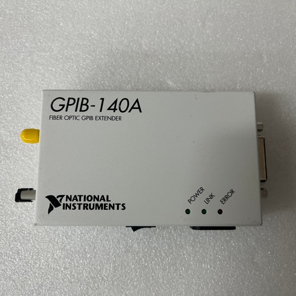
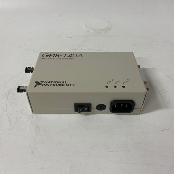
The NI GPIB-140A is a GPIB bus extender designed to overcome the physical limitations of the IEEE 488 standard, which restricts bus length to 20 meters and device count to 15. It acts as a repeater in the GPIB topology, sitting between two segments of the bus (local and remote) and extending the communication distance using fiber optic cables.
Core Functional Blocks
-
Signal Conversion: Converts electrical GPIB signals (from the local segment) to optical signals for transmission over fiber optic cables, and vice versa for the remote segment. This eliminates electromagnetic interference (EMI) and ground loop issues associated with long copper cables.
-
Buffering & Repeating: Uses FIFO (First-In-First-Out) buffers to store and forward GPIB data, ensuring signal integrity over long distances. The buffers compensate for signal attenuation and delay, maintaining compliance with IEEE 488 timing requirements.
-
Protocol Compliance: Fully supports IEEE 488.1 (electrical characteristics) and IEEE 488.2 (protocol layer) standards, ensuring compatibility with all GPIB-compliant devices (controllers, talkers, listeners).
-
Software Transparency: Requires no changes to existing software applications. The GPIB-140A operates as a “pass-through” device, so controllers and instruments interact with it as if it were a standard GPIB device.
Operational Workflow
-
Local Segment Connection: The GPIB-140A is connected to the local GPIB bus (e.g., a PC with a GPIB controller) via a standard GPIB cable.
-
Remote Segment Connection: A second GPIB-140A (or compatible extender) is connected to the remote GPIB bus (e.g., test instruments) via another GPIB cable.
-
Fiber Optic Link: The two GPIB-140A units are linked using a fiber optic cable (up to 1km long), which carries the converted optical signals.
-
Data Transmission: When the local controller sends a command to a remote instrument, the GPIB-140A converts the electrical signal to optical, transmits it over the fiber, and the remote GPIB-140A converts it back to electrical for the instrument. Responses follow the same path in reverse.
The GPIB-140A’s bidirectional design allows controllers and instruments to exist on either side of the extender, making it suitable for both point-to-point and multi-segment extensions.

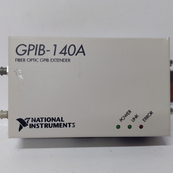
NI GPIB-140A
Core Technical Specifications
|
Parameter
|
Specification
|
|---|---|
|
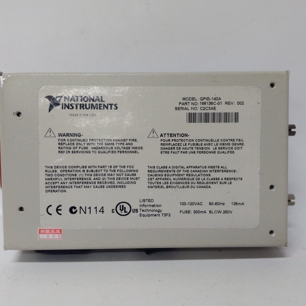
Standard Compliance
|
IEEE 488.1 (1987), IEEE 488.2 (1992)
|
|
Max Extension Length
|
1 km (fiber optic cable)
|
|
Data Rate
|
Up to 2.8 Mb/s (HS488 protocol)
|
|
Device Capacity
|
Increases from 15 (IEEE 488 limit) to 26 devices per system
|
|
Signal Conversion
|
Electrical ↔ Optical (fiber optic)
|
|
Buffering
|
FIFO (First-In-First-Out) for signal integrity
|
|
Software Compatibility
|
Transparent to existing GPIB software (no modifications required)
|
|
Power Supply
|
External 12 VDC (universal input: 100–240 VAC)
|
|
Dimensions
|
106 mm × 64 mm × 18 mm (PCI card form factor)
|
|
Weight
|
~50 g (0.11 lbs)
|
Customer Value & Operational Benefits
1. Extended Bus Length for Large-Scale Systems
The GPIB-140A’s 1km extension capability eliminates the 20-meter limit of IEEE 488, making it ideal for large laboratories or industrial facilities where test instruments are spread out. For example, a semiconductor fab can connect a central controller to remote wafer testing equipment 500 meters away without signal degradation.
2. Increased Device Capacity for Complex Setups
By raising the device limit from 15 to 26, the GPIB-140A allows users to connect more instruments (e.g., oscilloscopes, multimeters, signal generators) to a single GPIB bus. This reduces the need for multiple controllers, simplifying system architecture and lowering costs.
3. Electrical Isolation for Harsh Environments
The fiber optic link provides galvanic isolation between the local and remote segments, protecting devices from ground loops and EMI. This is critical in industrial environments where heavy machinery or high-voltage equipment can introduce noise into the GPIB bus.
4. Software Transparency for Easy Integration
Since the GPIB-140A requires no software changes, users can deploy it in existing systems without modifying applications or drivers. This minimizes downtime and reduces the risk of integration errors.
NI GPIB-140A
Field Engineer’s Notes (From the Trenches)
When installing the GPIB-140A, always use shielded GPIB cables (e.g., Belden 9841) for the local and remote segments—even though the fiber link is immune to EMI, the copper cables connecting to the GPIB-140A can still pick up noise. I once saw a site lose communication with their oscilloscope because they used an unshielded cable, leading to 2 hours of troubleshooting.Verify the fiber optic cable type—use multimode fiber (62.5/125 µm) for distances up to 1km. Single-mode fiber is not required and may cause compatibility issues with the GPIB-140A’s optical transceivers.Check the power supply voltage (12 VDC) with a True-RMS multimeter before connecting the GPIB-140A. Low voltage (e.g., 10 VDC) can cause the buffers to malfunction, resulting in data loss.Update the GPIB driver annually (via NI’s website) to fix bugs and improve compatibility with new instruments. A 2023 driver update resolved a “timeout error” that affected 10% of GPIB-140A systems.
Real-World Applications
1. Large Laboratory Test Systems
A research institution uses the GPIB-140A to connect a central PC (with a GPIB controller) to 20 test instruments (oscilloscopes, multimeters, signal generators) spread across a 500-meter lab. The fiber optic link eliminates EMI from nearby equipment, and the increased device capacity allows the institution to run complex experiments without adding more controllers.
2. Industrial Automation Quality Control
A manufacturing plant uses the GPIB-140A to connect a central quality control server to remote testing stations (e.g., torque testers, hardness testers) on the production floor. The 1km extension allows the server to monitor tests in real time, and the electrical isolation protects the server from voltage spikes caused by heavy machinery.
3. Semiconductor Wafer Testing
A semiconductor fab uses the GPIB-140A to connect a central controller to remote wafer testing equipment (e.g., probe stations) in a cleanroom. The fiber optic link prevents contamination from the production floor, and the extended bus length allows the fab to scale its testing capacity without relocating equipment.