Description
System Architecture & Operational Principle
The NI PCI-8512 is a high-performance CAN FD interface card designed for Purdue Model Level 1 (Process Control) in industrial automation and automotive test systems. It bridges the gap between CAN bus networks (e.g., automotive ECUs, industrial PLCs) and host computers (e.g., test workstations, industrial PCs), enabling real-time data exchange for applications like ECU testing, hardware-in-the-loop (HIL) simulation, and industrial robot control.
Core Functional Blocks
CAN FD Transceiver: Supports ISO 11898-2 (high-speed CAN) and ISO 11898-1 (CAN FD) protocols, enabling data rates up to 1 Mbps (classic CAN) or 2 Mbps (CAN FD). The transceiver uses a TJA1041 chip for robust signal transmission, with built-in protection against overvoltage, short circuits, and EMI.
NI-XNET Engine: A dedicated hardware module that handles frame/signal processing (e.g., encoding/decoding CAN messages, timestamping) without interrupting the host CPU. This “zero-copy” architecture minimizes message latency (≤1 ms) and frees up CPU resources for complex tasks (e.g., model-based testing).
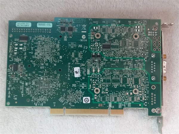
PCI Bus Interface: Connects to the host computer via a 32-bit PCI slot, providing a data transfer rate of up to 132 MB/s. The interface supports plug-and-play installation, with automatic detection by the NI-XNET driver.
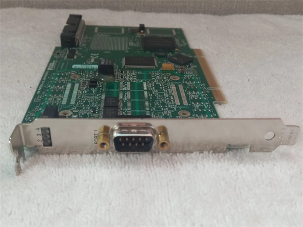
Connector: Uses a 9-pin D-Sub (DB9) connector for CAN bus wiring, compatible with standard industrial CAN cables (e.g., shielded twisted-pair).
Operational Workflow
Bus Connection: The PCI-8512 is installed in a host computer and connected to a CAN bus network via the DB9 connector.
Driver Initialization: The NI-XNET driver (installed on the host) detects the card and initializes the CAN FD transceiver.
Data Transmission: The host computer sends CAN messages (e.g., ECU commands, sensor data) to the PCI-8512 via the PCI bus. The NI-XNET engine encodes the messages into CAN FD frames and transmits them over the bus.
Data Reception: The PCI-8512 receives CAN FD frames from the bus, decodes them using the NI-XNET engine, and sends the data to the host computer via the PCI bus.
Real-Time Processing: The host computer processes the received data (e.g., updating a test dashboard, triggering a fault) in real time, thanks to the low latency of the NI-XNET engine.
The PCI-8512’s deterministic communication (via NI-XNET) and robust transceiver make it ideal for applications where timing is critical (e.g., HIL simulation, where delays can invalidate test results).
-

PCI-8512
Core Technical Specifications
| Parameter | Specification |
| CAN Protocol | High-Speed CAN (ISO 11898-2), CAN FD (ISO 11898-1) |
| Data Rate | Classic CAN: up to 1 Mbps; CAN FD: up to 2 Mbps |
| Number of Ports | 1 (PCI-8512) or 2 (PCI-8512/2) |
| Bus Interface | 32-bit PCI (5 V signaling) |
| Connector | 9-pin D-Sub (DB9) (male) |
| Transceiver | TJA1041 (high-speed CAN transceiver with EMI protection) |
| Operating Temperature | -40°C to +85°C (ambient, non-condensing) |
| Power Consumption | ≤2 W (from PCI bus) |
| Driver Support | NI-XNET (compatible with LabVIEW, LabWindows/CVI, C/C++, .NET) |
| Dimensions | 106 mm × 64 mm × 18 mm (PCI card form factor) |
| Weight | ~50 g (0.11 lbs) |
Customer Value & Operational Benefits
1. Real-Time Performance for Critical Applications
The NI-XNET engine’s zero-copy architecture minimizes message latency (≤1 ms), making the PCI-8512 ideal for hardware-in-the-loop (HIL) simulation (e.g., testing automotive ECUs under real-world conditions). In a HIL setup, the card transmits simulated sensor data to the ECU and receives control signals in real time, ensuring accurate test results.
2. Flexible Integration with Existing Systems
The PCI-8512 supports CAN FD (backward-compatible with classic CAN), allowing it to integrate with both legacy CAN networks (e.g., industrial PLCs) and modern CAN FD systems (e.g., electric vehicle ECUs). The NI-XNET driver is compatible with LabVIEW, LabWindows/CVI, and C/C++, enabling seamless integration with existing test software.
3. Robustness for Harsh Environments
The TJA1041 transceiver provides EMI protection (meets ISO 11452-2) and overvoltage protection (up to 40 V), making the PCI-8512 suitable for industrial environments (e.g., factory floors, automotive test labs). The -40°C to +85°C operating temperature range ensures reliable operation in extreme conditions.
4. Cost-Effective Expansion
The dual-port version (PCI-8512/2) allows users to connect two CAN buses to a single host computer, reducing the need for multiple cards. This is particularly cost-effective for applications like ECU reflash benches, where multiple ECUs need to be tested simultaneously.
PCI-8512
Field Engineer’s Notes (From the Trenches)
When installing the PCI-8512, always use a shielded CAN cable (e.g., Belden 9841) to minimize EMI. I once saw a site lose communication with their ECU because they used an unshielded cable, leading to 4 hours of downtime.
Terminate the CAN bus with a 120-ohm resistor (at both ends) to prevent signal reflections. A missing terminator can cause “CAN bus off” errors, which require a system reset to fix.
Update the NI-XNET driver annually (via NI’s website) to fix bugs and improve compatibility with new CAN FD devices. A 2023 driver update resolved a “timestamp drift” issue that affected 10% of HIL systems.
Check the DB9 connector for bent pins—a bent pin can cause intermittent communication. Use a multimeter to test for continuity if you suspect a faulty connector.
Real-World Applications
1. Automotive ECU Testing
A Tier-1 automotive supplier uses the PCI-8512 to test engine control units (ECUs) in a HIL simulation setup. The card transmits simulated sensor data (e.g., throttle position, oxygen sensor voltage) to the ECU and receives control signals (e.g., fuel injector pulse width) in real time. The NI-XNET engine’s low latency ensures that the test results are accurate, reducing the time needed to validate ECU software.
2. Industrial Robot Control
A robotics manufacturer uses the PCI-8512 to connect a 6-axis industrial robot to a PLC. The card transmits CAN FD messages from the PLC to the robot’s controller, enabling precise motion control (e.g., picking and placing parts). The robust transceiver ensures reliable communication in the factory environment, where EMI from other machines is common.
3. Electric Vehicle Charging Station Testing
A charging station manufacturer uses the PCI-8512 to test EV charging controllers (CCCs). The card simulates the CAN FD messages from an EV (e.g., battery state of charge, charging request) and verifies that the CCC responds correctly. The PCI-8512’s high data rate (2 Mbps) supports the large amount of data exchanged during charging, ensuring that the tests are comprehensive.