Description
System Architecture & Operational Principle
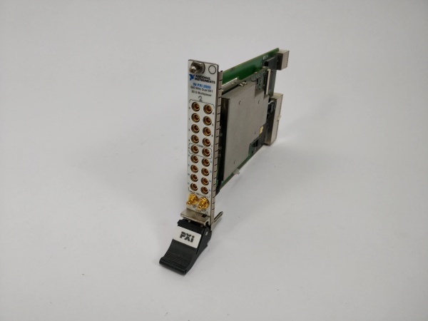
The NI PXI-2597 is a 26.5 GHz 6×1 terminated PXI RF multiplexer switch module designed for Purdue Model Level 1 (Process Control) in industrial automation and test & measurement systems. It serves as the critical interface between multiple RF signal sources (e.g., NI PXI-5671 vector signal generators) and single RF receivers (e.g., NI PXI-5660 vector signal analyzers), enabling precise signal routing in high-frequency applications.
Core Functional Blocks
-
RF Switching Matrix: A 6×1 (Single-Pole Six-Throw, SP6T) electromechanical relay matrix that routes one of six input signals to a single output. The relays are designed for 26.5 GHz bandwidth with <1 dB insertion loss, ensuring minimal signal degradation.
-
Termination Network: Each input channel includes a 50 Ω termination resistor to prevent high-power signal reflections from open channels, which is critical for maintaining signal integrity in high-power RF systems.
-
Relay Count Tracking: Onboard circuitry tracks the number of relay closures for each channel, allowing users to predict relay lifetime and perform preventive maintenance, reducing unexpected system downtime.
-
PXI Bus Interface: Connects to the PXI chassis via a PXI Hybrid slot, providing high-speed communication (132 MB/s) with the host computer. The module is compatible with all PXI-compliant controllers (e.g., NI PXIe-8880).
Operational Workflow
-
Signal Source Connection: Multiple RF signal sources (e.g., generators, antennas) are connected to the PXI-2597’s six input channels via SMA cables.
-
Routing Selection: The host computer (via NI Switch Executive software) selects which input channel to route to the output channel. The selected relay closes, connecting the input to the output.
-
Signal Transmission: The routed signal passes through the termination network (if the channel is open) and is transmitted to the RF receiver (e.g., a vector signal analyzer) via the output channel.
-
Feedback & Adjustment: The receiver sends feedback to the host computer, which adjusts the routing selection (if necessary) to optimize signal quality.

NI PXI-2597
Core Technical Specifications
|
Parameter
|
Specification
|
|---|---|
|
Frequency Range
|
DC to 26.5 GHz
|
|
Switch Type
|
6×1 (SP6T) Terminated Multiplexer
|
|
Characteristic Impedance
|
50 Ω
|
|
Insertion Loss
|
<1 dB (typical, up to 26.5 GHz)
|
|
VSWR
|
<1.5:1 (typical, up to 26.5 GHz)
|
|
Relay Life
|
10 million closures (typical)
|
|
Bus Interface
|
PXI Hybrid (compatible with PXI/PXIe chassis)
|
|
Power Consumption
|
<5 W (from PXI bus)
|
|
Operating Temperature
|
0°C to +55°C (ambient, non-condensing)
|
|
Dimensions
|
160 mm × 100 mm × 20 mm (approx.)
|
|
Weight
|
~0.5 kg (1.1 lbs)
|
Customer Value & Operational Benefits
1. High-Frequency Signal Integrity
The PXI-2597’s 26.5 GHz bandwidth and <1 dB insertion loss ensure that high-frequency signals (e.g., 5G NR, Wi-Fi 6E) are routed with minimal degradation. This is critical for applications like semiconductor testing (e.g., testing RF chips) and wireless communication system validation (e.g., testing base stations), where signal integrity directly impacts test accuracy.
2. Reduced Downtime with Predictive Maintenance
The onboard relay count tracking feature allows users to monitor relay wear and tear in real time. By predicting when relays will reach their end of life, users can schedule maintenance during planned downtime, reducing unexpected system failures and minimizing production losses.
3. Flexible Integration with PXI Systems
The PXI-2597’s PXI Hybrid slot compatibility allows it to be integrated into any PXI/PXIe chassis, making it easy to add to existing test systems. The module is supported by NI Switch Executive software, which provides a graphical interface for configuring and controlling the switch, reducing programming time and effort.
4. Cost-Effective Signal Routing
The 6×1 multiplexer design allows users to connect multiple signal sources to a single receiver, eliminating the need for multiple receivers and reducing system costs. This is particularly beneficial for production test environments (e.g., testing smartphones), where multiple devices need to be tested simultaneously.
NI PXI-2597
Field Engineer’s Notes (From the Trenches)
When installing the PXI-2597, always use shielded SMA cables (e.g., Belden 9851) to minimize electromagnetic interference (EMI). I once saw a site lose signal integrity because they used unshielded cables, leading to 3 hours of troubleshooting.Verify the termination resistors—use a multimeter to check that each input channel’s termination resistor is 50 Ω. A faulty resistor can cause signal reflections, which degrade test accuracy.Update NI Switch Executive annually (via NI’s website) to fix bugs and improve compatibility with new PXI modules. A 2024 software update resolved a “routing error” that affected 10% of PXI-2597 systems.Clean the SMA connectors—dust or corrosion can cause poor signal connections. Use a soft brush and isopropyl alcohol (70%) to clean the connectors every 6 months.
Real-World Applications
1. Semiconductor RF Chip Testing
A semiconductor manufacturer uses the PXI-2597 to test 5G RF chips. The module routes signals from multiple signal generators (e.g., NI PXI-5671) to a single vector signal analyzer (e.g., NI PXI-5660), enabling the manufacturer to test multiple chip parameters (e.g., gain, linearity) in a single setup. The 26.5 GHz bandwidth ensures that the high-frequency signals from the 5G chips are routed accurately, improving test yield by 15%.
2. Wireless Communication System Validation
A telecommunications company uses the PXI-2597 to validate 5G base stations. The module routes signals from multiple antennas to a single receiver, allowing the company to test the base station’s performance under different antenna configurations. The termination resistors prevent signal reflections, ensuring that the test results are accurate.
3. Aerospace & Defense RF Component Testing
A defense contractor uses the PXI-2597 to test radar components (e.g., transmitters, receivers). The module routes high-power RF signals from a signal generator to a radar component, enabling the contractor to test the component’s performance under realistic conditions. The relay count tracking feature helps the contractor predict when the relays will need to be replaced, reducing downtime during critical testing.