Description
1. Detailed Parameter Table
| Parameter Name | Parameter Value |
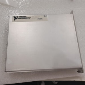
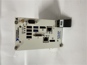
| Product Model | PXI-6713 |
| Manufacturer | National Instruments (NI) |
| Product Category | 16-Channel Analog Output Module |
| Output Channels | 16 analog output channels, software-configurable as single-ended |
| Resolution | 16-bit |
| Output Ranges | ±10 V, ±5 V, ±2.5 V, ±1 V, ±0.5 V, 0-10 V, 0-5 V, 0-2 V, 0-1 V |
| Maximum Update Rate | 1 MS/s (aggregate), 62.5 kS/s per channel (when updating all 16 channels) |
| Output Current | ±5 mA per channel (maximum), 20 mA total for all channels |
| Settling Time | 10 µs to 0.01% of full scale |
| Output Impedance | 0.1 Ω (typical) |
| Triggering | Digital triggering (start/stop triggers via PXI trigger lines or PFI signals) |
| FIFO Buffer Size | 8 kS |
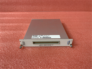
| Connector Type | 68-pin VHDCI (Very High-Density Cable Interconnect) |
| Physical Dimensions | 6.3 x 3.9 in |
| Weight | 7.6 oz |
| Operating Temperature Range | 0 to 55 °C |
| Storage Temperature Range | -20 to 70 °C |
| Humidity Range | 5 to 95% non-condensing |
| Calibration Interval | 1 year |
| Software Compatibility | LabVIEW, LabWindows/CVI, Measurement Studio, Visual Studio (C/C++, C#) |
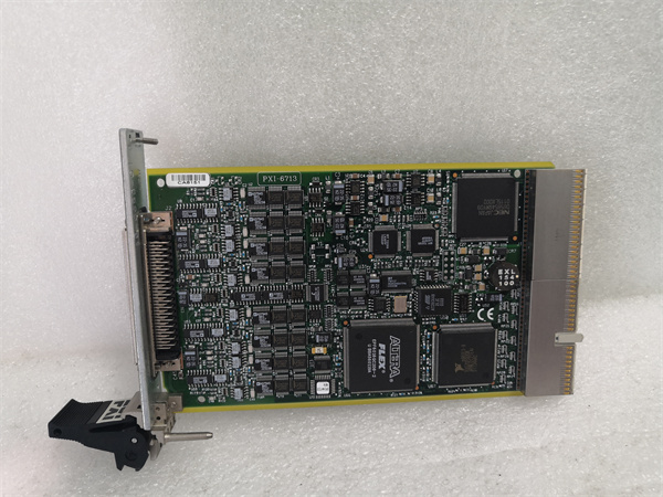
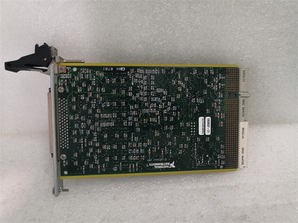
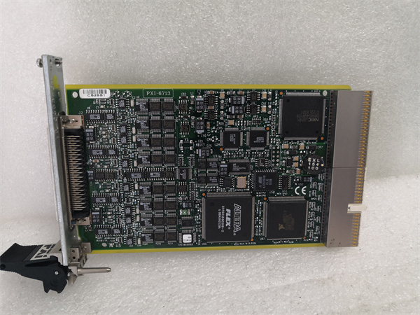
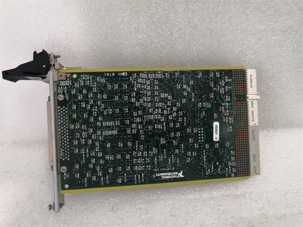
NI PXI-6713
2. Product Introduction
The NI PXI-6713 is a high-performance 16-channel analog output module designed for the PXI platform, tailored for applications requiring precise voltage generation across multiple channels. As part of NI’s analog output solutions, it excels in scenarios where synchronized, multi-channel signal generation is critical—from industrial control systems to automated test equipment.
Each of the 16 channels on the PXI-6713 delivers 16-bit resolution, ensuring accurate voltage output across a range of selectable ranges (e.g., ±10 V to 0-1 V). This versatility allows the module to drive a variety of devices, from actuators and valves in manufacturing lines to signal simulators in electronics testing. For example, in a automotive sensor test setup, the PXI-6713 can generate simulated sensor signals (such as throttle position or pressure readings) to validate the performance of engine control units.
With an aggregate update rate of 1 MS/s, the PXI-6713 can update all 16 channels simultaneously at 62.5 kS/s per channel, making it ideal for generating dynamic waveforms. Its integration with PXI trigger lines enables synchronization with other modules (e.g., DAQ or timing modules like the PXI-6602), ensuring coordinated operation in complex systems—such as generating stimulus signals while capturing response data with a DAQ module.
3. Core Advantages and Technical Highlights
High-Density, Multi-Channel Performance
The PXI-6713’s 16 channels in a single PXI slot maximize system density, reducing the footprint of test and control systems. This is especially valuable in compact setups, such as portable test rigs or space-constrained industrial enclosures. For instance, in a battery testing facility, the module can independently control the charge/discharge profiles of 16 battery cells, streamlining the testing process without requiring multiple modules.
Precise Voltage Generation
With 16-bit resolution and tight output accuracy, the PXI-6713 ensures minimal error in generated signals. Its low output impedance (0.1 Ω typical) minimizes signal distortion when driving loads, such as transducers or amplifiers. In medical device testing, for example, it can generate precise biopotential signals (mimicking ECG or EEG waveforms) with sub-millivolt accuracy, critical for validating diagnostic equipment.
Fast Update and Settling Times
The module’s 1 MS/s aggregate update rate and 10 µs settling time enable the generation of high-frequency dynamic signals. In aerospace simulation, this allows the PXI-6713 to generate real-time control signals for flight simulators, where rapid changes in actuator commands (e.g., aileron or rudder positions) must be simulated with minimal delay to ensure realistic training scenarios.
Flexible Triggering and Synchronization
Support for digital triggering via PXI trigger lines or PFI signals allows the PXI-6713 to synchronize with external events or other PXI modules. For example, when paired with the PXI-6602 timing module, it can start generating a waveform precisely when a sensor detects a specific condition (e.g., a temperature threshold), ensuring that stimulus and response measurements are time-aligned in automated test sequences.
4. Typical Application Scenarios
Industrial Control Systems
In manufacturing, the PXI-6713 controls variable-speed drives, valves, and actuators by generating analog setpoints. For a chemical processing plant, it can adjust flow rates across 16 pipelines by outputting precise voltage signals to proportional control valves, maintaining optimal reaction conditions. The module’s multi-channel capability allows simultaneous control of multiple processes, improving efficiency and reducing system complexity.
Automated Test Equipment (ATE)
In electronics manufacturing, the PXI-6713 generates test stimuli for circuit boards and components. It can simulate sensor inputs (e.g., temperature, pressure) to validate the performance of embedded systems, such as automotive ECUs or industrial controllers. By automating signal generation across 16 channels, it speeds up testing throughput in high-volume production lines.
Aerospace and Defense Simulation
Aerospace engineers use the PXI-6713 in hardware-in-the-loop (HIL) simulations to replicate flight conditions. It generates analog signals mimicking sensor outputs (e.g., airspeed, altitude) for testing avionics systems, ensuring they respond correctly to changing flight parameters. The module’s fast update rate ensures that simulated signals keep pace with real-time changes in the HIL environment.
Scientific Research
In physics and materials science labs, the PXI-6713 generates control signals for experimental setups. For example, it can precisely adjust the voltage across electrodes in a plasma physics experiment, controlling plasma density with microvolt-level precision. Its multi-channel capability allows researchers to independently control multiple parameters (e.g., temperature, pressure, and magnetic field) in complex experiments.
NI PXI-6713
5. Related Model Recommendations
PXI Chassis
The PXI-6713 requires a PXI chassis, such as the NI PXI-1045 (a 18-slot chassis with high-power capacity) or PXI-1071 (a compact 7-slot chassis). These chassis provide power and a high-speed backplane for synchronization with other modules, essential for building integrated test systems.
Timing and DAQ Modules
Pair the PXI-6713 with the PXI-6602 timing module for precise synchronization of signal generation with external events. For complete test setups, add a DAQ module like the PXI-6115 to measure the response of devices under test to the signals generated by the PXI-6713, creating a closed-loop test system.
Signal Conditioning Modules
For applications requiring higher current outputs, use the NI SCXI-1121 (a 4-channel programmable current source) with the PXI-6713. The PXI-6713 controls the SCXI-1121 via analog signals, enabling the generation of currents up to 1 A—useful for driving large actuators or heating elements.
Cables and Accessories
The PXI-6713 uses a 68-pin VHDCI connector, compatible with cables like the NI SHC68-68-EPM (shielded for noise-sensitive environments) or 197784-01 (ruggedized for industrial use). These cables ensure reliable signal transmission between the module and external devices, minimizing noise in critical applications.
6. Installation, Commissioning and Maintenance Instructions
Installation Preparation
Before installing the PXI-6713, power off the PXI chassis and ensure a static-free workspace. Use an anti-static wristband to prevent ESD damage. Align the module with the chassis guide rails and gently insert it until fully seated, then secure with front panel screws. Use shielded cables to connect the module to external devices, ensuring that load impedances are compatible with the module’s output capabilities (≥ 500 Ω recommended to avoid overload).
Commissioning Steps
Power on the chassis and launch NI MAX to detect the PXI-6713. Configure output ranges and channel settings via software. Calibrate the module using NI’s calibration utility to verify output accuracy across all ranges—use a precision DMM (e.g., NI PXI-4071) to measure generated voltages and confirm they match setpoints within tolerance. Test synchronization by triggering the module with a PXI-6602 and verifying that signal generation starts as expected.
Maintenance Suggestions
Regularly inspect the PXI-6713 for loose connectors or dust buildup; clean vents monthly with compressed air. Check output accuracy annually using a calibrated DMM, re-calibrating if deviations exceed specifications. If signals are distorted, verify load impedances and cable integrity—replace damaged cables to restore performance. For persistent issues, refer to the user manual or contact NI technical support.
7. Service and Guarantee Commitment
NI backs the PXI-6713 with a 3-year standard warranty, covering defects in materials and workmanship. During the warranty period, NI provides free repairs or replacements for qualifying issues. Technical support is available via online resources (knowledgebase, forums), email, and phone, with experts assisting in configuration, calibration, and integration with other PXI modules. For out-of-warranty units, NI offers calibration and repair services to extend operational life. With a focus on reliability, the PXI-6713 is designed to deliver consistent performance in critical applications, supported by NI’s global service network.