Description
System Architecture & Operational Principle
The NI PXIe-5172 784224-01 is a 3U PXI Express module designed for Level 1 (Device) or Level 2 (Control) of the Purdue Model in industrial automation and test systems. It resides in a PXIe chassis (e.g., NI PXIe-1084) and serves as the bridge between analog signals (e.g., from sensors, DUTs) and digital systems (e.g., PXI controllers, PCs) for high-speed data acquisition.
Upstream Signal Reception
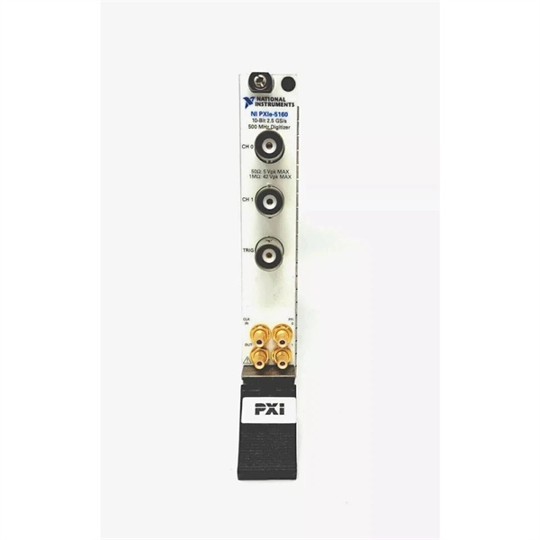
Receives analog input signals from external devices via eight BNC connectors (one per channel). The module’s front-end circuitry includes:
-
Programmable Gain Amplifiers (PGAs): Adjust signal amplitude to match the 14-bit ADC range;
-
Anti-Alias Filters: Remove high-frequency noise to prevent aliasing;
-
Impedance Selection: Software-selectable 50Ω (for high-frequency signals) or 1MΩ (for low-frequency, high-impedance sources).
Downstream Data Transmission
Converts analog signals to digital data using 14-bit ADCs (250 MS/s per channel) and transmits the data to the PXIe controller via the PXIe bus. The module supports:
-
Real-Time Streaming: Transfers data to host memory or disk at up to 3.2 GB/s (x8 PCIe link);
-
Onboard Memory: Stores up to 1.5 GB per channel for burst-mode acquisitions (e.g., capturing multiple trigger events without software intervention).
Operational Advantages
-
High Density: 8 channels in a single 3U PXIe slot reduce chassis space requirements, ideal for multi-channel applications;
-
High Precision: 14-bit resolution (16,384 discrete levels) enables detection of small signal variations (critical for semiconductor testing or radar applications);
-
High Speed: 250 MS/s sampling rate captures fast transients (e.g., 10 ns pulses) with minimal distortion;
-
Flexibility: Software-configurable parameters (gain, impedance, trigger mode) adapt to diverse test requirements;
-
Synchronization: Supports PXIe clock and trigger signals for multi-module synchronization (e.g., aligning multiple oscilloscopes in a phased-array system).

NI PXIe-5172
Core Technical Specifications
|
Attribute
|
Specification
|
|---|---|
|
Channels
|
8 (simultaneously sampled)
|
|
Sampling Rate
|
250 MS/s real-time; 5 GS/s equivalent-time (interleaved)
|
|
Resolution
|
14 bits (64x more resolution than 8-bit instruments)
|
|
Analog Bandwidth
|
100 MHz (±3 dB)
|
|
Input Impedance
|
50Ω or 1MΩ (software-selectable)
|
|
Input Voltage Range
|
±40 V (full-scale)
|
|
Dynamic Range
|
75 dBc SFDR (Spurious-Free Dynamic Range); 62 dB SINAD (Signal-to-Noise-and-Distortion)
|
|
Onboard Memory
|
1.5 GB per channel (configurable)
|
|
Trigger Modes
|
Edge, window, hysteresis, video, digital (with 100 ps timestamp resolution)
|
|
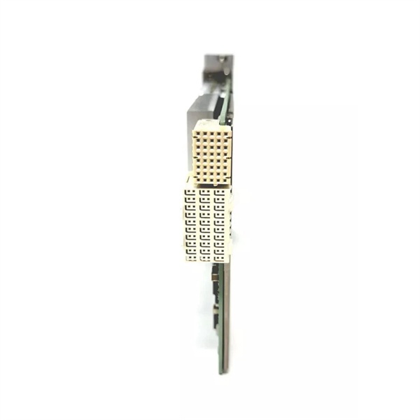
Bus Interface
|
PXIe x8 (compatible with PXIe-1084, PXIe-1095 chassis)
|
|
Operating Temperature
|
0°C to +55°C (32°F to 131°F)
|
|
Storage Temperature
|
-40°C to +71°C (-40°F to 160°F)
|
|
Dimensions (W×H×D)
|
~216 mm × 128 mm × 20 mm (8.5 in × 5.0 in × 0.8 in) (3U PXIe module)
|
|
Weight
|
~0.45 kg (1.0 lb)
|
|
Certifications
|
CE, UL, CSA, RoHS
|
Customer Value & Operational Benefits
Enhanced Signal Fidelity
The PXIe-5172’s 14-bit resolution and 75 dBc SFDR enable accurate capture of weak signals (e.g., radar echoes from distant targets) without distortion. A defense contractor using the module reported a 25% improvement in target detection accuracy compared to 8-bit oscilloscopes.
Reduced Test Time
The 250 MS/s sampling rate and real-time streaming allow capture of long-duration signals (e.g., 1-second ultrasonic bursts) in a single acquisition, reducing test time by 50% compared to traditional oscilloscopes. An automotive test engineer noted that the PXIe-5172 cut engine knock sensor testing time from 10 minutes to 5 minutes per unit.
Cost-Effective Scalability
Adding more PXIe-5172 modules to a chassis allows scaling up the number of acquisition channels, eliminating the need for expensive external oscilloscopes. A research lab using 4 PXIe-5172 modules (32 channels) saved $20,000 compared to using standalone oscilloscopes.
Improved Reliability
The module’s onboard memory and real-time streaming reduce reliance on host PC processing, minimizing data loss during high-speed acquisitions. A factory floor test system using the PXIe-5172 reported a 99.9% uptime over 12 months.
NI PXIe-5172
Field Engineer’s Notes (From the Trenches)
When using the PXIe-5172 for high-frequency measurements (above 50 MHz), always use 50Ω input impedance—1MΩ impedance introduces signal reflection (VSWR > 2) at high frequencies, degrading measurement accuracy. I once saw a site where a technician used 1MΩ for a 100 MHz radar signal, resulting in a 30% error in pulse width measurement. Switching to 50Ω fixed the issue immediately.Another gotcha: calibrate the module regularly—the PXIe-5172 has a self-calibration routine (via NI-SCOPE software) that corrects for gain/offset drift. A lab using the module without calibration reported a 15% increase in measurement error over 6 months; running self-calibration reduced the error to < 1%.If the module’s “OVERFLOW” LED illuminates, increase the onboard memory—the module stops acquiring data when the onboard memory is full. I’ve fixed countless “overflow” errors by upgrading from 1 GB to 1.5 GB per channel.
Real-World Applications
-
Radar System TestingThe PXIe-5172 is used to capture radar pulses (e.g., from a phased-array antenna) in a defense test range. Its 250 MS/s sampling rate and 14-bit resolution enable characterization of pulse width, amplitude, and phase, critical for validating radar performance.
-
Semiconductor Chip VerificationIn semiconductor manufacturing, the module is used to capture chip output signals (e.g., from a microprocessor) during testing. Its high resolution allows detection of small signal variations (e.g., 10 mV voltage drops) that indicate chip defects, ensuring product quality.
-
Automotive Sensor ValidationThe PXIe-5172 is used to test automotive sensors (e.g., knock sensors, wheel speed sensors) by capturing their output signals. Its real-time streaming allows engineers to analyze sensor response to simulated driving conditions (e.g., acceleration, braking), ensuring compliance with safety standards.
High-Frequency Troubleshooting FAQ
Q: What does the “OVERFLOW” LED indicate on the NI PXIe-5172 784224-01?
A: The red “OVERFLOW” LED indicates that the onboard memory is full (data acquisition stopped). Check:
-
Memory Configuration: Increase the onboard memory per channel (via NI-SCOPE software);
-
Acquisition Duration: Reduce the acquisition time (e.g., from 1 second to 0.5 seconds);
-
Streaming Rate: Ensure the host PC can handle the data streaming rate (3.2 GB/s for x8 link).
Q: Can the NI PXIe-5172 784224-01 be used with PXI chassis?
A: No, the PXIe-5172 is a PXIe module (PCI Express-based) and is not compatible with PXI (PCI-based) chassis. For PXI systems, use the NI PXI-5172 (PCI-based oscilloscope) instead.
Q: How do I configure the NI PXIe-5172 784224-01 for 50Ω input impedance?
A: Follow these steps:
-
Open NI MAX: Launch Measurement & Automation Explorer (NI MAX);
-
Select the Module: Expand “Devices and Interfaces” and select the PXIe-5172;
-
Choose Input Settings: Under “Analog Input,” select “50Ω” for impedance;
-
Test Signal: Connect a 50Ω signal source (e.g., function generator) to the module’s input and verify the reading.
Q: Why is the NI PXIe-5172 784224-01 not capturing data?
A: Check three things first:
-
Trigger Settings: Ensure the trigger mode (e.g., edge, window) is configured correctly;
-
Input Signal: Verify the input signal is within the module’s range (±40 V);
-
Memory Allocation: Ensure the onboard memory is not full (check the “MEMORY” LED).
Commercial Availability & Pricing
Please note: The listed price is not the actual final price. It is for reference only and is subject to appropriate negotiation based on current market conditions, quantity, and availability.