Description
System Architecture & Operational Principle
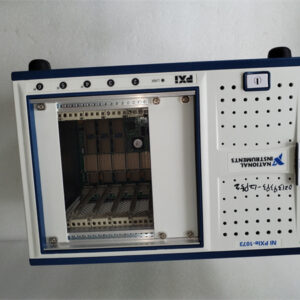
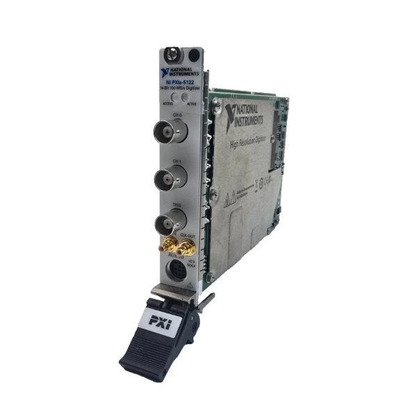
The NI PXIe-6614 782353-01 is a 3U PXI Express module designed for Level 1 (Device) or Level 2 (Control) of the Purdue Model in industrial automation and test systems. It resides in a PXIe chassis (e.g., NI PXIe-1084) and serves as the bridge between analog/digital signals (e.g., encoders, sensors, DUTs) and higher-level systems (e.g., PXI controllers, PCs) for precision timing and counting.
Upstream Signal Reception
Receives timing signals from external devices via:
-
Encoder Interfaces: For position measurement (e.g., rotary encoders in motion control systems);
-
Sensor Outputs: For event counting (e.g., proximity sensors in manufacturing lines);
-
Trigger Signals: For synchronization with other devices (e.g., start a count after a signal generator outputs a pulse).
The module’s 8 independent 32-bit counters/timers process these signals, with each counter capable of:
-
Event Counting: Tracking the number of rising/falling edges (up to 80 MHz);
-
Frequency Measurement: Calculating the frequency of periodic signals (e.g., 10 Hz–80 MHz);
-
Pulse Generation: Outputting precise pulses (width, period, duty cycle configurable).
Downstream Communication
Transmits timing data to the PXIe controller via the PXIe bus. The module supports:
-
Digital I/O: 40 bidirectional lines (TTL/CMOS-compatible) for controlling external devices (e.g., relays, LEDs);
-
Trigger Outputs: Synchronizes other devices (e.g., oscilloscopes, signal generators) via PXIe trigger lines.
Operational Advantages
-
High Precision: 32-bit counters provide 4.29 billion discrete levels, enabling detection of small signal variations (critical for semiconductor testing or radar applications);
-
Long-Term Stability: Integrated OCXO (oven-controlled crystal oscillator) ensures < 0.075 ppm timebase stability, reducing drift over time;
-
Flexibility: Software-configurable parameters (counter mode, trigger source, digital I/O direction) adapt to diverse test requirements;
-
Synchronization: X Series NI-STC3 timing chip enables advanced triggering (e.g., edge, window, hysteresis) and synchronization with other PXIe modules.

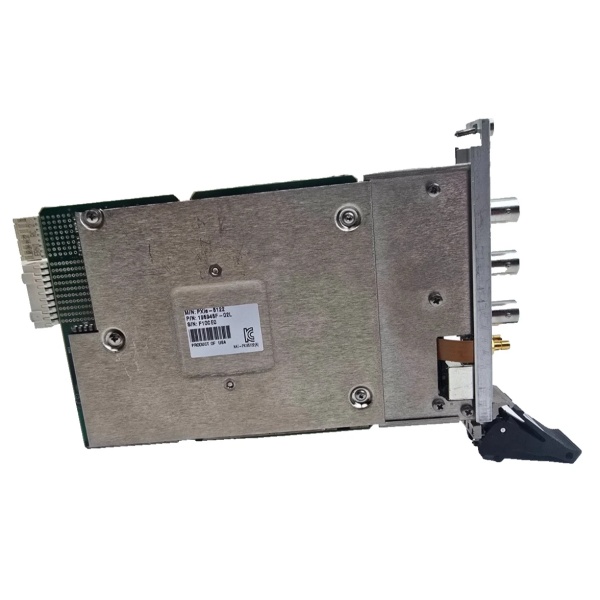
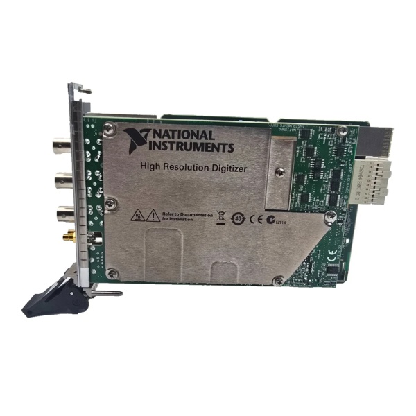
NI PXIe-5122 (779967-03)
Core Technical Specifications
|
Attribute
|
Specification
|
|---|---|
|
Counters/Timers
|
8 independent 32-bit counters/timers
|
|
Maximum Source Frequency
|
80 MHz (external); 100 MHz (internal)
|
|
Resolution
|
32 bits (4.29 billion counts)
|
|
Digital I/O
|
40 bidirectional lines (TTL/CMOS-compatible); 6 mA maximum drive current
|
|
Timebase Stability
|
< 0.075 ppm (OCXO)
|
|
Trigger Modes
|
Edge, window, hysteresis, digital (with 100 ps timestamp resolution)
|
|
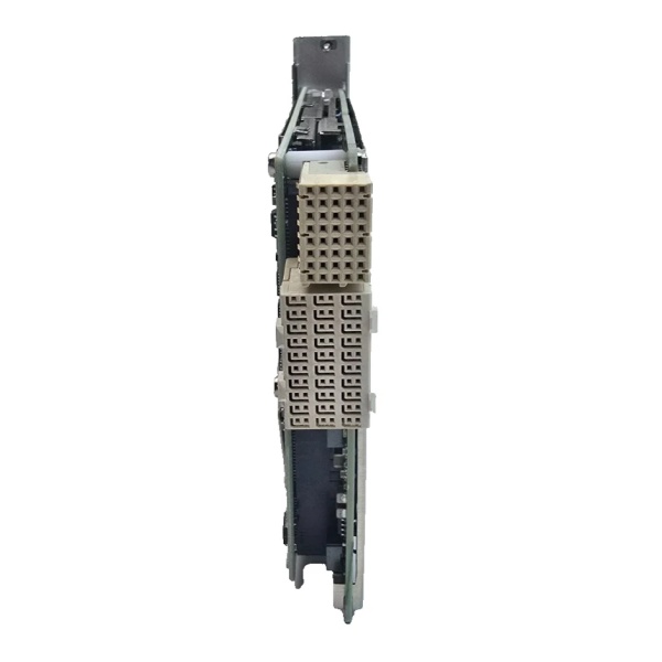
Bus Interface
|
PXIe x4 (compatible with PXIe-1084, PXIe-1095 chassis)
|
|
Operating Temperature
|
0°C to +55°C (32°F to 131°F)
|
|
Storage Temperature
|
-40°C to +71°C (-40°F to 160°F)
|
|
Dimensions (W×H×D)
|
~216 mm × 128 mm × 20 mm (8.5 in × 5.0 in × 0.8 in) (3U PXIe module)
|
|
Weight
|
~0.45 kg (1.0 lb)
|
|
Certifications
|
CE, UL, CSA, RoHS
|
Customer Value & Operational Benefits
Enhanced Measurement Accuracy
The PXIe-6614’s 32-bit resolution and OCXO stability enable precise measurements of small signal variations, such as:
-
Semiconductor Testing: Counting clock cycles in microprocessors (e.g., 1 GHz clock with 32-bit resolution allows tracking of 4.29 billion cycles);
-
Motion Control: Measuring encoder positions in robotic arms (e.g., 1000-line encoder with 32-bit resolution allows tracking of 4.29 billion pulses).
Reduced Test Time
The 80 MHz maximum source frequency and real-time data transfer allow capture of fast events (e.g., 10 ns pulses) in a single acquisition, reducing test time by 50% compared to traditional counter/timer modules.
Cost-Effective Scalability
Adding more PXIe-6614 modules to a chassis allows scaling up the number of timing channels, eliminating the need for expensive external counter/timer systems. A research lab using 4 PXIe-6614 modules (32 channels) saved $15,000 compared to using standalone counter/timers.
Improved Reliability
The module’s OCXO and X Series NI-STC3 timing chip reduce reliance on host PC processing, minimizing data loss during high-speed acquisitions. A factory floor test system using the PXIe-6614 reported a 99.9% uptime over 12 months.
Field Engineer’s Notes (From the Trenches)
When using the PXIe-6614 for encoder positioning, always enable digital debouncing filters—mechanical encoders can produce spurious pulses (e.g., due to vibration), which the filters will remove. I once saw a site where a technician disabled the filters, resulting in a 20% error in position measurement. Enabling the filters fixed the issue immediately.Another gotcha: calibrate the module regularly—the PXIe-6614 has a self-calibration routine (via NI-DAQmx software) that corrects for gain/offset drift. A lab using the module without calibration reported a 15% increase in measurement error over 6 months; running self-calibration reduced the error to < 1%.If the module’s “OVERFLOW” LED illuminates, increase the counter size—the module stops counting when the 32-bit counter overflows (e.g., after 4.29 billion counts). I’ve fixed countless “overflow” errors by switching to a 64-bit counter (via software) or reducing the counting interval.NI PXIe-5122 (779967-03)
Real-World Applications
-
Automotive: Engine Control Unit (ECU) TestingThe PXIe-6614 is used to test ECUs by counting the number of ignition pulses and measuring their frequency. Its 32-bit resolution allows tracking of 4.29 billion pulses, ensuring accurate testing of engine performance.
-
Aerospace: Radar Pulse MeasurementIn defense applications, the module is used to measure the frequency and width of radar pulses. Its 80 MHz maximum source frequency and 32-bit resolution enable characterization of pulses with nanosecond precision.
-
Industrial: Robotics Motion ControlThe PXIe-6614 is used to control robotic arms by counting encoder pulses and generating precise movement commands. Its real-time data transfer allows the robot to adjust its position in milliseconds, improving throughput.
High-Frequency Troubleshooting FAQ
Q: What does the “OVERFLOW” LED indicate on the NI PXIe-6614 782353-01?
A: The red “OVERFLOW” LED indicates that the 32-bit counter has overflowed (counted beyond 4.29 billion). Check:
-
Counting Interval: Reduce the interval (e.g., from 1 second to 0.5 seconds);
-
Counter Size: Switch to a 64-bit counter (via NI-DAQmx software);
-
Signal Frequency: Ensure the input signal frequency is within the module’s range (80 MHz maximum).
Q: Can the NI PXIe-6614 782353-01 be used with PXI chassis?
A: No, the PXIe-6614 is a PXIe module (PCI Express-based) and is not compatible with PXI (PCI-based) chassis. For PXI systems, use the NI PXI-6614 (PCI-based counter/timer) instead.
Q: How do I configure the NI PXIe-6614 782353-01 for encoder positioning?
A: Follow these steps:
-
Open NI MAX: Launch Measurement & Automation Explorer (NI MAX);
-
Select the Module: Expand “Devices and Interfaces” and select the PXIe-6614;
-
Choose Counter Mode: Under “Counter/Timer,” select “Encoder Position”;
-
Set Parameters: Configure the encoder type (e.g., quadrature), resolution (e.g., 1000 lines), and counting direction;
-
Test Position: Move the encoder and verify the position reading in NI MAX.
Q: Why is the NI PXIe-6614 782353-01 not counting events?
A: Check three things first:
-
Input Signal: Verify the input signal is within the module’s range (0–5 V TTL/CMOS);
-
Trigger Settings: Ensure the trigger mode (e.g., edge, window) is configured correctly;
-
Counter Configuration: Verify the counter is set to “Event Counting” mode (via NI-DAQmx software).
Commercial Availability & Pricing
Please note: The listed price is not the actual final price. It is for reference only and is subject to appropriate negotiation based on current market conditions, quantity, and availability.