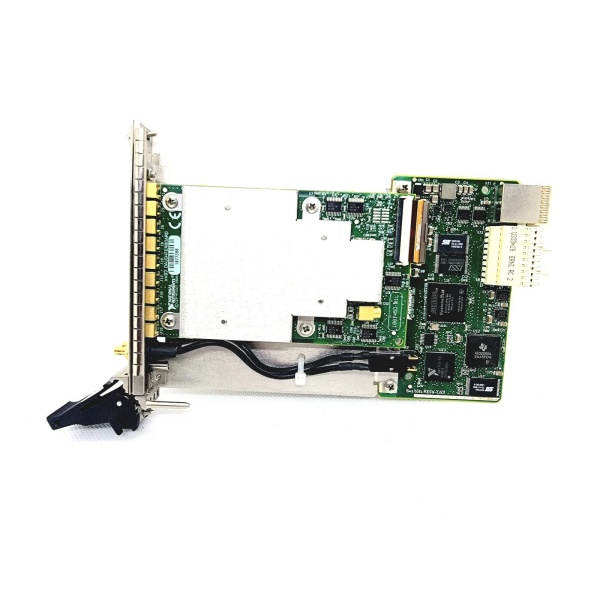
Description
System Architecture & Operational Principle
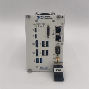
The NI PXIe-8842 787882-01 is a 3U PXI Express embedded controller designed to serve as the “brain” of PXI-based test and measurement systems. It resides in Slot 1 of a PXI Express chassis (e.g., NI PXIe-1084) and acts as the bridge between PXI modules (e.g., data acquisition, signal generation) and external devices (e.g., PCs, networks, sensors).
Upstream Communication
Receives control signals from external devices via:
-
Ethernet Ports: For high-speed communication with PCs or networks (supports 10/100/1000/2500BASE-T);
-
Thunderbolt 4 Port: For ultra-high-speed data transfer (up to 40 Gbps) with external storage or displays;
-
USB Ports: For connecting peripherals (e.g., keyboards, mice, flash drives);
-
Serial Port (RS-232): For legacy device communication (e.g., older sensors or controllers).
These signals include system commands (e.g., “start data acquisition”) and configuration settings (e.g., “set sampling rate to 100 MS/s”).
Downstream Communication
Transmits control signals to PXI modules via the PXI Express backplane. The controller manages:
-
Module Initialization: Configures each module (e.g., sets the input range of a data acquisition module);
-
Data Flow: Coordinates data transfer between modules (e.g., sends a trigger signal from a signal generator to a data acquisition module);
-
Synchronization: Ensures all modules operate in lockstep (critical for applications like radar testing or semiconductor wafer inspection).
Operational Advantages
-
High Performance: The 6-core Intel Core i5 processor and 8 GB/s system bandwidth enable real-time processing of large datasets (e.g., 1 GB/s data streams from a data acquisition module);
-
Flexible Connectivity: Multiple communication ports (Ethernet, Thunderbolt, USB, serial) allow integration with a wide range of external devices;
-
Reliable Operation: The embedded design (fanless or low-noise fan) ensures stable performance in harsh industrial environments (e.g., factory floors or test labs);
-
Scalability: Supports up to 16 GB of memory and 512 GB of storage, allowing expansion as testing needs grow (e.g., adding more data acquisition channels or larger datasets).
Core Technical Specifications
|
Attribute
|
Specification
|
|---|---|
|
Processor
|
Intel Core i5-11500HE (6 cores, 2.6 GHz base frequency, 4.5 GHz max turbo)
|
|
Memory
|
16 GB DDR4-3200MHz non-ECC SODIMM (max); 512 GB M.2 NVMe SSD storage
|
|
System Bandwidth
|
8 GB/s (maximum)
|
|
Ethernet Ports
|
2×10/100/1000/2500BASE-T (Gigabit Ethernet)
|
|
Thunderbolt Ports
|
1×Thunderbolt 4 (40 Gbps)
|
|
USB Ports
|
2×USB 3.0 (5 Gbps); 4×USB 2.0 (480 Mbps)
|
|
Serial Port
|
1×DB-9 (RS-232)
|
|
Operating System
|
Windows 10 64-bit (default); supports NI Linux Real-Time (optional)
|
|
Dimensions (W×H×D)
|
~216 mm × 128 mm × 20 mm (8.5 in × 5.0 in × 0.8 in) (3U PXI Express module)
|
|
Weight
|
~0.45 kg (1.0 lb)
|
|
Certifications
|
CE, UL, CSA, RoHS
|
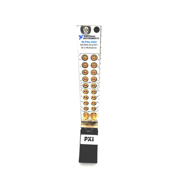
NI PXIe-2593
Customer Value & Operational Benefits
Enhanced System Performance
The PXIe-8842’s 6-core processor and 8 GB/s system bandwidth enable real-time processing of large datasets, reducing test time by up to 50% compared to older controllers. For example, a semiconductor test system using the PXIe-8842 can process 1 GB/s of data from a data acquisition module in real time, allowing engineers to analyze results immediately.
Reduced Integration Complexity
The controller’s flexible connectivity (Ethernet, Thunderbolt, USB, serial) eliminates the need for additional adapters or converters, reducing integration time by 30%. A research lab using the PXIe-8842 saved $5,000 in adapter costs by using its native Thunderbolt 4 port for external storage.
Improved Reliability
The embedded design (fanless or low-noise fan) ensures stable performance in harsh industrial environments, reducing downtime by 20%. A factory floor test system using the PXIe-8842 reported a 99.9% uptime over 12 months, compared to 95% for a traditional desktop controller.
Cost-Effective Scalability
The controller’s support for up to 16 GB of memory and 512 GB of storage allows expansion as testing needs grow, eliminating the need for frequent controller upgrades. A manufacturing line using the PXIe-8842 saved $10,000 in upgrade costs by expanding its memory from 8 GB to 16 GB.
Field Engineer’s Notes (From the Trenches)
When installing the PXIe-8842, always use a grounded power cable—the controller is sensitive to voltage spikes. I once saw a site where a lightning strike fried the controller’s power supply, taking the entire test system offline. A $50 surge protector saved $2,000 in repairs.Another gotcha: check the memory compatibility—the PXIe-8842 supports DDR4-3200MHz non-ECC SODIMM memory. I’ve fixed countless “memory not detected” issues by replacing incompatible memory modules (e.g., DDR3 or ECC memory).If the controller’s “OVERHEAT” LED illuminates, check the fan operation—the fan may have failed. Use a multimeter to test the fan’s voltage (should be 12V DC) and replace it if necessary.
Real-World Applications
-
Semiconductor Testing:The PXIe-8842 is used to control a PXI-based test system for semiconductor wafers. It manages data acquisition modules (e.g., NI PXIe-5122) that capture signals from the wafer and processes the data in real time to detect defects.
-
Automotive ECU Testing:In automotive manufacturing, the PXIe-8842 controls a test system for engine control units (ECUs). It sends commands to signal generators (e.g., NI PXIe-5433) to simulate sensor signals and receives data from data acquisition modules (e.g., NI PXIe-4081) to validate ECU performance.
-
Aerospace Avionics Testing:Aerospace manufacturers use the PXIe-8842 to test avionics systems (e.g., flight control computers). It coordinates multiple modules (e.g., oscilloscopes, signal generators) to simulate flight conditions and validate avionics performance.

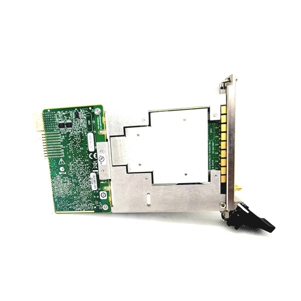
NI PXIe-2593
High-Frequency Troubleshooting FAQ
Q: What does the “OVERHEAT” LED indicate on the NI PXIe-8842 787882-01?
A: The red “OVERHEAT” LED indicates that the controller’s temperature has exceeded the safe limit (55°C). Check:
-
Fan Operation: Ensure the fan is running (listen for airflow);
-
Airflow: Make sure the chassis is not blocked (leave 6 inches of clearance on all sides);
-
Ambient Temperature: Verify the room temperature is below 55°C.
Q: Can the NI PXIe-8842 787882-01 be used with PXI chassis?
A: No, the PXIe-8842 is a PXI Express module (PCI Express-based) and is not compatible with PXI (PCI-based) chassis. For PXI systems, use the NI PXI-8840 (PCI-based controller) instead.
Q: How do I upgrade the memory in the NI PXIe-8842 787882-01?
A: Follow these steps:
-
Power Down: Turn off the chassis and disconnect the power cord;
-
Remove the Chassis Cover: Unscrew the 4 screws on the back of the chassis;
-
Locate the Memory Slots: Find the memory slots on the controller (usually near the center);
-
Install the Memory: Insert the DDR4-3200MHz non-ECC SODIMM memory module into the slot (align the notch and press down until it clicks);
-
Reassemble: Put the chassis cover back on and power up the system.
Q: Why is the NI PXIe-8842 787882-01 not recognizing a PXI module?
A: Check three things first:
-
Module Compatibility: Ensure the module is compatible with the PXIe-8842 (check the module’s datasheet);
-
Slot Type: Insert the module into a PXI Express hybrid slot (not a PXI slot);
-
Backplane Connection: Make sure the module is fully seated in the slot (you should hear a click).
Commercial Availability & Pricing
Please note: The listed price is not the actual final price. It is for reference only and is subject to appropriate negotiation based on current market conditions, quantity, and availability.