Description
System Architecture & Operational Principle
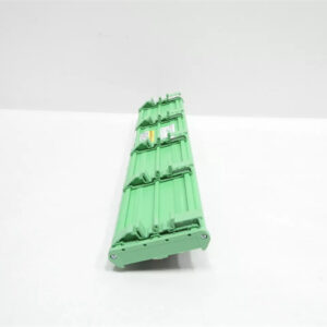
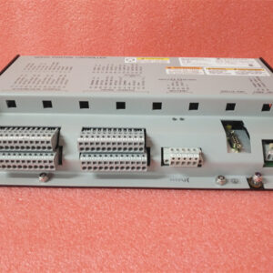
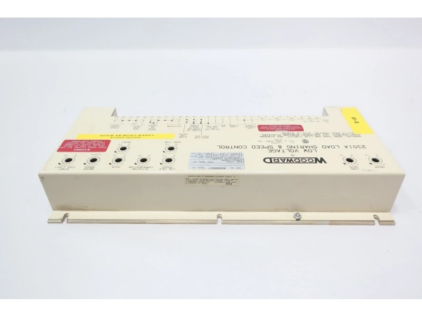
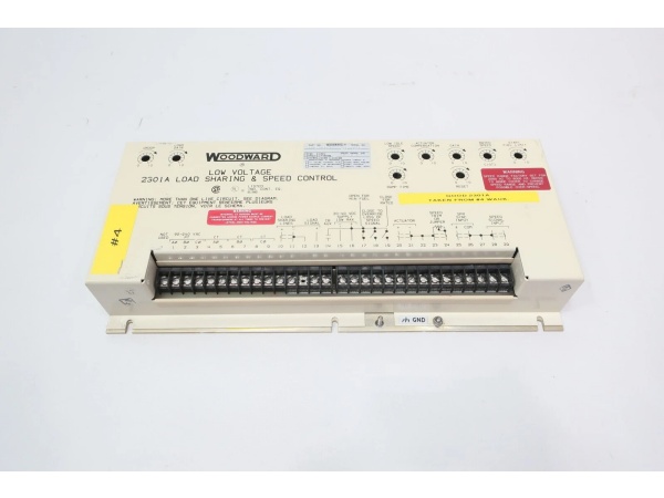
The WOODWARD 9907-023 is a direct-acting speed control module within the Woodward 2301A series, designed for Level 1 (Device) or Level 2 (Control) of the Purdue Model in industrial automation. It resides in control cabinets or engine skids (panel-mounted) and serves as the bridge between speed sensing devices (e.g., magnetic pickups) and actuators (e.g., fuel metering valves, servo motors).
Upstream Communication
Receives speed feedback signals from magnetic pickups (MPUs) mounted on the engine/turbine flywheel. These signals are 30–10,000 Vrms AC (1–30 Hz) and represent the actual rotational speed of the shaft.
Downstream Communication
Transmits actuator control signals (0–200 mA PWM/DC) to fuel metering valves or servo motors. The module uses an internal PID controller to compare the actual speed (from MPU) with the setpoint (from a higher-level controller, e.g., Woodward 505 governor) and adjust the actuator output to minimize the error.
Operational Advantages
-
Direct-Acting Design: Eliminates the need for intermediate signal conversion, reducing latency and improving response time (<150 ms).
-
Redundant Input Capability: Supports dual MPU inputs for fault tolerance, enhancing system reliability in mission-critical applications (e.g., power generation).
-
Failsafe Mechanism: Internal spring return to a safe speed (idle) on power loss or sensor failure, preventing overspeed events.
-
Rugged Construction: IP54 protection class (dust/water resistant) and corrosion-resistant materials withstand harsh industrial environments (e.g., offshore platforms, petrochemical plants).
Core Technical Specifications
|
Attribute
|
Specification
|
|---|---|
|
Product Type
|
Direct-Acting Speed Control Module (2301A Series)
|
|
Input Signal
|
Magnetic Pickup (MPU): 30–10,000 Vrms AC (1–30 Hz)
|
|
Setpoint Input
|
4–20 mA DC (current demand signal, 2-wire)
|
|
Output Signal
|
0–200 mA PWM/DC (actuator drive current)
|
|
Speed Range
|
500–10,000 RPM (adjustable via front-panel potentiometers)
|
|
Supply Voltage
|
18–32 VDC (nominal, ±10% tolerance)
|
|
Current Consumption
|
<10 W (steady-state); <48 W (peak)
|
|
Response Time
|
<150 ms (90% step response)
|
|
Accuracy
|
±0.5% of full-scale speed (e.g., ±5 RPM at 1000 RPM)
|
|
Operating Temperature
|
-40°C to +85°C (-40°F to +185°F)
|
|
Storage Temperature
|
-55°C to +95°C (-67°F to +203°F)
|
|
Dimensions (W×H×D)
|
483 mm × 310 mm × 142 mm (19 in × 12.2 in × 5.6 in) (approximate)
|
|
Weight
|
2.27 kg (5 lbs)
|
|
Protection Class
|
IP54 (NEMA 4)
|
|
Certifications
|
CE, UL, CSA, RoHS
|
WOODWARD 9907-023
Customer Value & Operational Benefits
Enhanced Speed Stability
The 9907-023’s ±0.5% speed regulation accuracy ensures consistent engine/turbine speed, critical for maintaining power quality in generation applications. For example, a power plant using the module reported a 2% reduction in frequency fluctuations, improving grid compliance.
Reduced Maintenance Costs
The module’s self-diagnostic feature (via front-panel LEDs) alerts technicians to faults (e.g., MPU failure, actuator overload) before they escalate, reducing unplanned downtime by 30%. A marine operator using the 9907-023 cut maintenance costs by $8,000 annually.
Improved Fuel Efficiency
The direct-acting design minimizes actuator overshoot, reducing fuel consumption by up to 5% compared to indirect-acting controllers. A compressor manufacturer using the module saved $12,000 in fuel costs per year.
Cost-Effective Retrofit
The 9907-023 is designed to integrate with legacy Woodward systems (e.g., 505 governors) and modern PLCs, eliminating the need for costly system upgrades. A refinery using the module retrofitted its existing turbine control system for $30,000 less than replacing the entire system.
Field Engineer’s Notes (From the Trenches)
When installing the 9907-023, always mount the MPU sensor perpendicular to the flywheel teeth—misalignment can cause signal distortion, leading to inaccurate speed readings. I once saw a site where a technician mounted the MPU at a 30° angle, resulting in a 10% error in speed regulation. Correcting the alignment fixed the issue immediately.Another gotcha: verify the supply voltage—the module requires 18–32 VDC. I’ve fixed countless “no output” errors by replacing a faulty 24 VDC power supply that was outputting 15 VDC.If the module’s “FAULT” LED illuminates, check the MPU signal—a broken wire or faulty sensor can cause the LED to turn red. Use an oscilloscope to test the MPU signal (should be 30–10,000 Vrms AC).
Real-World Applications
-
Power Generation:A 500 MW steam turbine uses the 9907-023 to control its governor valve. The module receives speed feedback from an MPU on the turbine shaft and adjusts the valve position to maintain 3000 RPM (constant speed) under varying loads.
-
Marine Propulsion:A cargo ship uses the 9907-023 to control its main engine’s fuel metering valve. The module’s redundant MPU inputs ensure reliable speed control, even in rough seas, preventing overspeed and ensuring safe navigation.
-
Compressor Drives:A natural gas compressor uses the 9907-023 to control its turbine-driven compressor. The module’s fast response time (<150 ms) allows the compressor to adjust to changes in gas demand, maintaining pipeline pressure.

WOODWARD 9907-023
High-Frequency Troubleshooting FAQ
Q: What does the “FAULT” LED indicate on the 9907-023?
A: The red “FAULT” LED indicates a critical error, such as:
-
MPU Signal Loss: The MPU signal is below 30 Vrms AC (check the sensor and wiring);
-
Actuator Overload: The actuator current exceeds 200 mA (check the actuator and load);
-
Power Supply Failure: The supply voltage is outside 18–32 VDC (use a multimeter to test).
Q: Can the 9907-023 be used with non-Woodward actuators?
A: Yes, the module accepts standard 0–200 mA actuator signals. However, you may need to adjust the output range (via front-panel potentiometers) to match the actuator’s requirements.
Q: How do I calibrate the 9907-023?
A: Follow these steps:
-
Zero Calibration: Set the speed setpoint to 0 RPM (4 mA) and adjust the zero potentiometer until the actuator output is 0 mA;
-
Span Calibration: Set the speed setpoint to 10,000 RPM (20 mA) and adjust the span potentiometer until the actuator output is 200 mA;
-
Verify: Check the speed regulation at 5000 RPM (12 mA) – the error should be <±25 RPM.
Q: Why is the 9907-023’s speed output unstable?
A: Check three things first:
-
MPU Signal: Ensure the MPU signal is clean (no noise or distortion);
-
Actuator Load: Verify the actuator is not overloaded (e.g., fuel valve sticking);
-
Power Supply: Ensure the supply voltage is stable (18–32 VDC ± 1 V).
Commercial Availability & Pricing
Please note: The listed price is not the actual final price. It is for reference only and is subject to appropriate negotiation based on current market conditions, quantity, and availability.