Description
System Architecture & Operational Principle
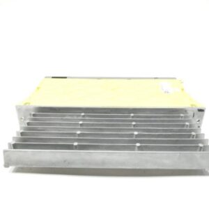
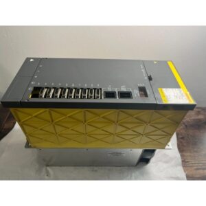
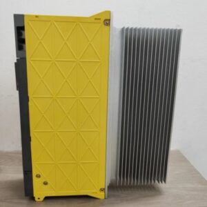
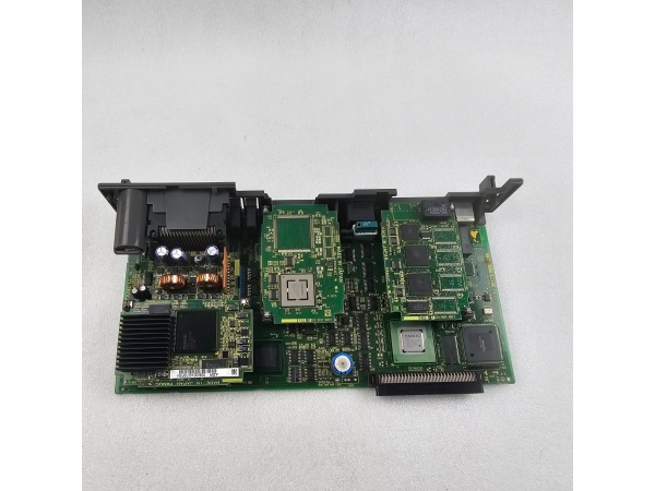
The Fanuc A16B-3200-0782 is the main PCB (central processing unit board) of the Fanuc R-30iB robot controller, designed for Level 1 (Device) or Level 2 (Control) of the Purdue Model in industrial automation. It resides in the robot controller cabinet (typically mounted on a DIN rail or panel) and serves as the bridge between human operators (via the teach pendant) and robot peripherals (e.g., servo motors, sensors, grippers).
Upstream Communication
Receives program commands from the teach pendant (via a serial or Ethernet link) and sensor data from robot-mounted devices (e.g., encoders, proximity switches). These signals are processed by the PCB’s microprocessor to generate motion control instructions.
Downstream Communication
Transmits motion control signals to servo amplifiers (via the FSSB (FANUC Serial Servo Bus)) and I/O signals to peripheral devices (e.g., grippers, solenoids). The PCB also sends status feedback (e.g., “program running,” “error detected”) to the teach pendant for operator monitoring.
Operational Advantages
-
High Integration: Combines the microprocessor, memory, and I/O interfaces into a single PCB, reducing cabinet space and wiring complexity.
-
Fast Processing: The 32-bit RISC microprocessor enables real-time execution of complex motion control algorithms (e.g., circular interpolation, spline interpolation).
-
Modular Design: Supports hot-swappable FROM/SRAM modules, allowing easy upgrades to increase program storage capacity.
Core Technical Specifications
|
Attribute
|
Specification
|
|---|---|
|
Product Type
|
Main PCB (Central Processing Unit Board)
|
|
Model Variant
|
A16B-3200-0782 (R-30iB Main Board)
|
|
Input Voltage
|
24 V DC (±10%, 10A max current)
|
|
Microprocessor
|
32-bit RISC (Fanuc custom)
|
|
Memory
|
Supports FROM/SRAM modules (32MB–128MB); onboard SRAM (16MB typical)
|
|
Communication Interfaces
|
FSSB (FANUC Serial Servo Bus), Ethernet (10/100 Mbps), RS-232C (serial)
|
|
Operating Temperature
|
0°C to +40°C (32°F to 104°F)
|
|
Storage Temperature
|
-20°C to +60°C (-4°F to 140°F)
|
|
Humidity Tolerance
|
5%–95% non-condensing
|
|
Dimensions (W×H×D)
|
~400 mm × 300 mm × 150 mm (15.7 in × 11.8 in × 5.9 in) (estimated)
|
|
Weight
|
~19 kg (41.9 lbs)
|
|
Certifications
|
CE, UL, CSA
|
|
Compatibility
|
Fanuc R-30iB series robot controllers (e.g., R-30iB Mate, R-30iB Premium)
|
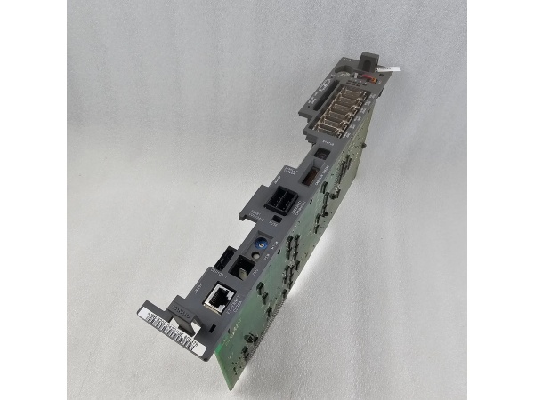
Fanuc A16B-3200-0782
Customer Value & Operational Benefits
Enhanced Robot Performance
The A16B-3200-0782’s fast processing speed and high integration enable precise motion control (e.g., ±0.01mm repeatability), which is critical for high-precision applications like automotive welding or electronics assembly.
Reduced Downtime
The modular design (hot-swappable FROM/SRAM modules) allows technicians to upgrade or replace the PCB without shutting down the robot, minimizing production losses. For example, a manufacturing plant can upgrade the program storage capacity during a lunch break, avoiding a 4-hour downtime.
Cost-Effective Maintenance
The PCB’s compatibility with R-30iB series controllers means that customers can use existing spare parts (e.g., FROM/SRAM modules) for repairs, reducing inventory costs. Additionally, the PCB’s long service life (≥5 years typical) minimizes the need for frequent replacements.
Compliance with Industry Standards
The PCB’s certifications (CE, UL, CSA) ensure it meets the rigorous requirements of industries like automotive, aerospace, and medical devices, making it a trusted choice for facilities seeking to adhere to regulatory or corporate safety standards.
Field Engineer’s Notes (From the Trenches)
When installing the A16B-3200-0782, always verify the FSSB cable connections—loose or reversed cables can cause communication errors (e.g., “FSSB link down” alarm). I once saw a site where a contractor swapped the FSSB cables between two robots, resulting in erratic motion. A simple check of the cable labels saved a 3-hour callout.Another gotcha: check the power supply voltage—the PCB requires 24 V DC (±10%). I once saw a site where a contractor connected it to a 12 V DC supply, resulting in a “no display” fault. Use a multimeter to confirm the input voltage before powering up.If the PCB’s “FAULT” LED is red, check the alarm log—the robot controller will store a fault code (e.g., “memory error,” “servo communication failure”) that indicates the problem. Use Fanuc’s Alarm Code Manual (B-65162) to diagnose the issue (e.g., code “12” indicates a memory error).
Real-World Applications
-
Automotive Manufacturing: Robotic Welding CellsA automotive assembly plant uses the A16B-3200-0782 to control a 6-axis robot for welding car frames. The PCB processes program commands from the teach pendant and sensor data from the robot’s encoders, enabling precise welding (±0.02mm accuracy). The FSSB bus transmits motion control signals to the servo amplifiers, ensuring smooth and accurate robot movement.
-
Electronics Manufacturing: Pick-and-Place RobotsAn electronics factory uses the A16B-3200-0782 to control a 4-axis robot for picking and placing microchips. The PCB’s fast processing speed enables the robot to handle 1000 parts per hour with ±0.01mm repeatability. The Ethernet interface allows remote monitoring and program updates from the factory’s SCADA system.

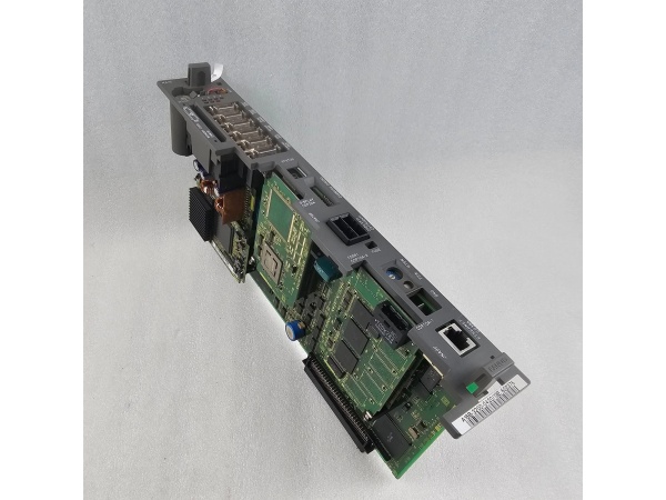
Fanuc A16B-3200-0782
High-Frequency Troubleshooting FAQ
Q: What does a “no display” fault indicate on the A16B-3200-0782?
A: A “no display” fault usually means:
-
Power Supply Issue: The 24 V DC power supply is not connected or is faulty (check the power cord and input voltage).
-
Display Driver Error: The PCB’s display driver is damaged (replace the display driver board).
-
Cable Connection: The FSSB or serial cable is loose or disconnected (check the cable connections).
Q: Can the A16B-3200-0782 be used with non-Fanuc robots?
A: No, the PCB is designed exclusively for Fanuc R-30iB series robots. It relies on Fanuc’s proprietary communication protocols (e.g., FSSB) for operation, so using it with non-Fanuc robots will result in compatibility issues.
Q: How do I replace the A16B-3200-0782?
A: Follow these steps:
-
Power Down: Turn off the robot controller and disconnect the PCB’s power cable.
-
Remove Old PCB: Unscrew the PCB from the controller cabinet (use a Phillips screwdriver).
-
Install New PCB: Secure the new A16B-3200-0782 to the cabinet and tighten the screws.
-
Connect Cables: Reconnect the FSSB, serial, and power cables.
-
Power Up: Turn on the robot controller and verify the PCB’s operation (check the “OK” LED).
Q: Why is the robot not executing programs correctly?
A: Check three things first:
-
Program Storage: Ensure the program is stored correctly in the FROM/SRAM module (use the teach pendant to verify).
-
Sensor Data: Check the robot’s encoders and proximity switches for proper operation (use a multimeter to test the signals).
-
PCB Status: Check the PCB’s “FAULT” LED—if it’s red, diagnose the issue using the alarm log (see FAQ above).
Commercial Availability & Pricing
Please note: The listed price is not the actual final price. It is for reference only and is subject to appropriate negotiation based on current market conditions, quantity, and availability.