Description
Detailed Parameter Table
| Parameter name | Parameter value |
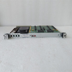
| Product model | MVME-712-11 |
| Manufacturer | Motorola (now integrated into Emerson’s industrial automation product portfolio) |
| Product category | Industrial Digital Output Module (VMEbus-compatible, high-load discrete control) |
| Digital Output Channels | 16 isolated digital output channels (grouped into 4 banks of 4 channels each, for finer load distribution) |
| Output Signal Type | Sourcing output (PNP); supports dry contact (load switching) and wet contact (direct voltage output); compatible with inductive/capacitive loads |
| Output Voltage Range | 12-36 VDC (continuous output); 5 VDC TTL-level output (configurable via software, no hardware jumpers required) |
| Output Current Capacity | 2 A per channel (continuous); 5 A per channel (peak, 150 ms duration); 4 A per channel bank (total current limit, preventing bank-level overloads) |
| Isolation Level | 3 kVrms galvanic isolation between output channels and VMEbus backplane; 2 kVrms isolation between channel banks (enhanced vs. MVME-712/M) |
| Bus Compatibility | Complies with VMEbus IEEE 1014-1987 standard (3U form factor); supports VMEbus A16/D16, A24/D16 address cycles; interrupt requests (IRQ 1-7, configurable) |
| Environmental Requirements | Operating temperature: -15°C to 70°C (5°F to 158°F); Storage temperature: -40°C to 85°C (-40°F to 185°F); Relative humidity: 5% to 95% (non-condensing, 40°C dew point); Vibration resistance: 5-500 Hz, 2.0 g (peak); Shock resistance: 60 g (peak, 10 ms duration) |
| Physical Size | 3U VMEbus form factor (100 mm x 160.02 mm / 3.94 in x 6.30 in); weight: 190 g (0.42 lbs) |
| Installation Method | VMEbus backplane mounting; compatible with 3U/6U VME chassis; requires VMEbus power supply (+5V, +12V) + dedicated +24V/+36V external power for high-load channels |
| Protection Features | Overcurrent protection (2.4 A per channel, self-resetting with adjustable trip time); short-circuit protection (latching, with remote reset via software); ESD protection (±25 kV contact, ±15 kV air) on terminals; over-temperature protection (90°C, auto-recovery); inductive load flyback protection (built-in freewheeling diodes) |
| Diagnostic Features | Built-in self-test (BIST) with detailed fault reporting (via VMEbus to SBC); LED indicators (power, bank status, channel fault, BIST result); software-accessible fault logs (overcurrent, short-circuit, overtemperature events) |
| Power Consumption | Typical: 8 W (at 25°C, 24 VDC output, 50% channel load); Maximum: 18 W (full channel load, 36 VDC) |
| Compatibility | Optimized for MVME series SBCs (MVME-147-023, MVME-162-001, MVME-243); works with MVME input modules (MVME-717, MVME-121) and power modules (MVME-050, MVME-051) |
| Response Time | ≤1.5 ms (output activation); ≤0.8 ms (output deactivation); latency consistent across all channels (±0.2 ms) |
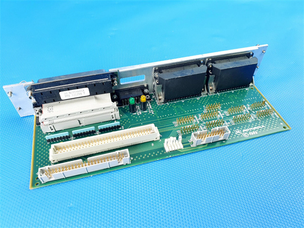
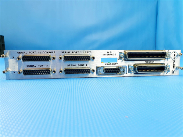
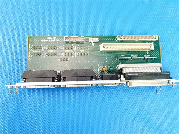
Motorola MVME-712/M
Product Introduction
The Motorola MVME-712-11 is a high-performance industrial digital output module developed by Motorola—a leader in legacy industrial automation—and now part of Emerson’s robust product ecosystem. As an enhanced variant of the MVME-712 series, it is engineered to address the demand for controlling high-current industrial loads (such as large motors, heavy-duty solenoids, and heating elements) in VMEbus-based control systems, filling the gap between standard output modules (like the MVME-712/M) and specialized power controllers.
Designed for rugged industrial environments where load stability and fault resilience are critical, the Motorola MVME-712-11 features 16 isolated channels with 2 A continuous current capacity, enhanced 3 kVrms isolation, and built-in flyback protection for inductive loads. In automation architectures, the Motorola MVME-712-11 acts as a “high-power executor”: it receives digital control commands from MVME series single-board computers (e.g., the MVME-162-001) that process input data from modules like the MVME-717, then delivers robust output signals to heavy actuators. For example, in a steel processing plant, after the MVME-717 detects a metal sheet in position via a proximity sensor, the MVME-162-001 sends a “clamp” command to the Motorola MVME-712-11, which activates a 24 VDC, 1.8 A hydraulic clamp solenoid. Its flyback protection prevents voltage spikes from the solenoid’s inductive load, safeguarding both the module and the central SBC—making it indispensable for heavy manufacturing, automotive, and aerospace applications.
Core Advantages and Technical Highlights
Enhanced Current Capacity for Heavy-Duty Loads: The Motorola MVME-712-11 delivers 2 A continuous current per channel (vs. 1 A for the MVME-712/M) and 5 A peak current (150 ms), enabling direct control of high-power devices without external relays or contactors. This eliminates the need for additional power modules, reducing system complexity and failure points. For instance, in a commercial HVAC system, the Motorola MVME-712-11 can directly control 16 small fan motors (each drawing 1.5 A at 24 VDC) or 8 larger damper actuators (2 A each), whereas the MVME-712/M would require external relays for these loads. The module’s 4-channel bank design also limits total current per bank to 4 A, preventing overloading of individual power circuits and enhancing system safety.
Advanced Isolation and Inductive Load Protection: A key upgrade in the Motorola MVME-712-11 is its 3 kVrms galvanic isolation (vs. 2.5 kVrms for MVME-712/M) between channels and the VMEbus backplane, plus 2 kVrms between banks—providing superior protection against ground loops and electrical interference in high-voltage environments (e.g., welding shops or power generation facilities). It also integrates built-in freewheeling diodes for each channel, which suppress voltage spikes caused by inductive load deactivation (common with solenoids, motors, or relays). Unlike the MVME-712/M (which requires external diodes for inductive loads), the Motorola MVME-712-11 simplifies wiring and eliminates the risk of damage from unprotected spike voltages—critical for extending the lifespan of both the module and connected actuators.
Software-Configurable Flexibility and Smart Diagnostics: The Motorola MVME-712-11 replaces hardware jumpers with software-configurable output voltages (5 VDC TTL or 12-36 VDC), allowing remote adjustment via the connected SBC (e.g., MVME-147-023) without physical access to the module—a major advantage for systems in hard-to-reach locations (e.g., offshore platforms or ceiling-mounted control cabinets). It also includes software-accessible fault logs that record overcurrent, short-circuit, and overtemperature events, enabling technicians to trace the root cause of issues (e.g., a repeated short-circuit on Channel 7 indicating a faulty actuator). The module’s BIST function provides detailed fault reporting (vs. basic pass/fail in MVME-712/M), such as identifying a specific bank’s isolation failure, reducing troubleshooting time from hours to minutes.
Wider Environmental Tolerance for Extreme Conditions: The Motorola MVME-712-11 operates in a broader temperature range (-15°C to 70°C vs. -10°C to 65°C for MVME-712/M) and withstands higher vibration (2.0 g peak) and shock (60 g peak), making it suitable for extreme environments like mining, construction, or outdoor industrial sites. For example, in a mining equipment control system, the module can operate reliably in underground tunnels with temperatures as low as -10°C or in above-ground enclosures reaching 65°C, whereas the MVME-712/M might experience performance degradation or shutdowns in these conditions. Its resistance to 95% humidity (non-condensing, 40°C dew point) also makes it ideal for food processing plants or marine applications where moisture is prevalent.
Typical Application Scenarios
The Motorola MVME-712-11 excels in industrial settings requiring high-power discrete control—including heavy manufacturing, automotive assembly, and aerospace component production. In a heavy machinery manufacturing plant, it is deployed to control 16 hydraulic lift actuators on a tractor assembly line. The Motorola MVME-712-11 receives “lift/lower” commands from the MVME-162-001 SBC (which processes input data from the MVME-717’s position sensors), then sends 24 VDC, 1.9 A signals to the actuators. Its 2 A continuous current capacity easily handles the actuators’ load, while flyback protection suppresses voltage spikes when the actuators deactivate. The module’s 3 kVrms isolation protects the MVME-162-001 from interference from nearby welding machines, ensuring precise control of lift positioning—critical for aligning tractor frames during assembly.
In automotive final assembly, the Motorola MVME-712-11 controls 16 battery charging relays for electric vehicle (EV) production. Each relay draws 1.2 A at 36 VDC, and the Motorola MVME-712-11’s 12-36 VDC range supports the plant’s 36 VDC power system. The MVME-147-023 SBC uses input data from the MVME-717 (monitoring battery presence) to send “charge/stop” commands to the Motorola MVME-712-11, which activates the relays to initiate charging. The module’s software-configurable voltage allows technicians to adjust output settings remotely if the plant switches to 24 VDC relays, avoiding downtime for hardware reconfiguration. Its short-circuit protection also prevents damage if a relay’s coil shorts, ensuring uninterrupted EV production.
In aerospace component testing, the Motorola MVME-712-11 controls 16 environmental chamber heaters (each 24 VDC, 1.7 A) for thermal cycling tests of aircraft parts. The MVME-162-001 SBC uses temperature sensor data (from the MVME-717) to send “heat/hold” commands to the Motorola MVME-712-11, which modulates the heaters to maintain temperatures between -50°C and 150°C. The module’s wide operating temperature range (-15°C to 70°C) withstands the chamber’s external heat, while its over-temperature protection (90°C) prevents overheating if a heater malfunctions. For test engineers, the Motorola MVME-712-11’s fault logs provide a record of heater performance, ensuring compliance with aerospace testing standards.
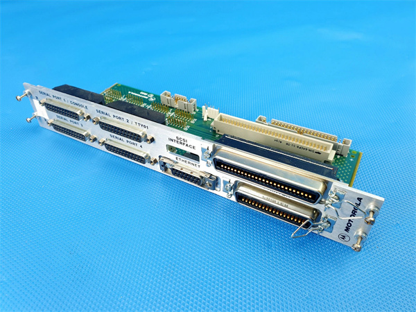
Motorola MVME-712/M
Related Model Recommendations
Motorola MVME-712/M: The base model in the MVME-712 series, with 1 A per channel (vs. 2 A for MVME-712-11). It is a cost-effective alternative for low-power loads (e.g., indicator lights, small relays) where the MVME-712-11’s capacity is unnecessary.
Motorola MVME-717: A complementary digital input module designed to pair with the Motorola MVME-712-11. The MVME-717 monitors actuator status (e.g., limit switches on hydraulic clamps), while the Motorola MVME-712-11 controls the actuators—forming a closed-loop high-power control system.
Motorola MVME-162-001: A high-performance SBC optimized for the Motorola MVME-712-11. Its 66 MHz 68060 processor efficiently sends control commands to the module and processes fault data, ideal for high-speed, high-load applications.
Motorola MVME-051: An industrial power supply module that powers the Motorola MVME-712-11’s high-load channels. Its 30 A +5V and 10 A +24V outputs ensure stable power for 2 A actuators, unlike the MVME-050 (20 A +5V).
Motorola MVME-910-3: An Ethernet communication module that works with the Motorola MVME-712-11. It transmits the module’s output status and fault logs to upper-level SCADA systems, enabling remote monitoring of high-power loads.
Motorola MVME-718-11: A higher-density variant of the Motorola MVME-712-11, with 32 output channels (4 banks of 8). It is an upgrade for large-scale systems (e.g., automotive assembly lines with 32 robots) needing more high-power outputs.
Motorola MVME-121: A mixed digital I/O module that complements the Motorola MVME-712-11. The MVME-121 handles low-power I/O (e.g., sensor inputs, small relays), while the Motorola MVME-712-11 manages high-power actuators.
Motorola MVME-243: A modern MVME series SBC that supports the Motorola MVME-712-11. Its 32-bit processor and expanded memory handle complex control logic for systems using multiple MVME-712-11 modules.
Installation, Commissioning and Maintenance Instructions
Installation preparation: Before installing the Motorola MVME-712-11, verify the VMEbus chassis supports 3U modules and provides stable +5V/+12V power; connect a dedicated +24V/+36V external power supply for high-load channels (use 14 AWG wire for power connections). Gather tools: anti-static wristband (to protect high-current circuits), torque screwdriver (for chassis mounting, 0.4 N·m), wire strippers, crimping tool (for terminal lugs), and a clamp meter (to measure load current). Ensure all power sources are disconnected, then clean the VME backplane connector with a dry, lint-free cloth to remove dust (debris can cause short-circuits in high-current paths). Align the Motorola MVME-712-11 with the chassis’ guide rails, slide it into the backplane until fully seated, and secure with screws. Use 16 AWG wire for output channels (to handle 2 A current) and separate output wiring from input/signal cables to reduce interference.
Maintenance suggestions: For daily upkeep of the Motorola MVME-712-11, inspect the LED indicators weekly—steady green power LED, illuminated bank LEDs (active channels), and no fault LED indicate normal operation. A red fault LED signals overcurrent/short-circuit; use the SBC’s software to access fault logs and identify the affected channel/bank. Clean the output terminals monthly with compressed air (low pressure, 30 PSI max) to remove dust and prevent contact resistance. Every 3 months, measure output current with a clamp meter to ensure channels are not operating above the 2 A continuous limit; derate loads if necessary (e.g., reduce duty cycle for 2 A actuators to 80% to prevent overheating). If a channel fails, first test the actuator for shorts (replace if defective) and reset the module via software; avoid disassembling the module, as internal high-power components carry residual charge. Store spare Motorola MVME-712-11 modules in anti-static bags in a climate-controlled environment (15°C to 25°C, 40% to 60% humidity) to preserve isolation and current-handling performance.
Service and Guarantee Commitment
The Motorola MVME-712-11 is backed by a 24-month factory warranty (extendable to 60 months via premium service contracts), covering defects in materials and workmanship—including faulty high-current channels, isolation circuit failures, and flyback diode malfunctions. If a defect is identified during the warranty period, we provide free replacement or repair (with a 48-hour turnaround for in-stock modules) to