Description
Detailed Parameter Table
| Parameter Name | Parameter Value |
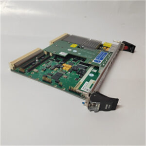
| Product Model | Motorola MVME709-1 |
| Manufacturer | Motorola (now part of Emerson’s industrial automation portfolio) |
| Product Category | VMEbus Specialized Communication Interface Module (dual-port RS-485/RS-422 + fiber-optic communication for long-distance, high-noise environments) |
| Interface Configuration | 2x RS-485/RS-422 serial ports (software-selectable mode); 2x fiber-optic ports (multimode, 850 nm wavelength); 8x digital I/O channels (4 input, 4 output, TTL/CMOS compatible) |
| Serial Port Specifications | Baud rate: 300 bps – 115.2 kbps (software-configurable); data bits: 7/8; parity: none/even/odd; stop bits: 1/2; max transmission distance: 1200 m (RS-485), 2 km (multimode fiber) |
| Fiber-Optic Specifications | Data rate: Up to 10 Mbps; link budget: -18 dBm (min); max distance: 2 km (62.5/125 µm multimode fiber); connector type: ST (straight tip) |
| Digital I/O Specifications | Input voltage range: 0–0.8 VDC (LOW), 2.0–5.5 VDC (HIGH); input current: 10 µA max per channel; output current: 20 mA sink/source per channel |
| Bus Standard | VMEbus (PICMG VME 1.4 compliant) – 16-bit address/data bus; slave-only mode; supports VMEbus interrupts (level 3–5) |
| Physical Dimensions | Standard 3U VME form factor (100 mm × 160 mm × 16 mm; L×W×H) – fits standard VME chassis slots |
| Power Requirements | +5 VDC (1.0 A typical, 1.5 A maximum); +12 VDC (0.3 A typical); passive heat dissipation (no fan) |
| Operating Temperature Range | -20°C – 70°C (-4°F – 158°F) (extended industrial environmental tolerance) |
| Product Status | Obsolete (discontinued by manufacturer; supported via aftermarket/refurbished services) |
| Compliance Standards | VMEbus 1.4; EIA/TIA-485/422; IEEE 802.3 (fiber-optic); FCC Class A (EMI); CE Mark; RoHS; IEC 61000-6-2/-4 (industrial EMC immunity/susceptibility) |
| Compatibility | Optimized for Motorola VME SBCs (MVME5500, MVME2434, MVME172-263/260); works with power modules (FAB 0340-1049, 01-W3324F)、communication modules (FLN4234A, MVME335)、I/O modules (MVME172PA-644SE, MVME-204A728-1) |
| On-Board Features | Per-port status LEDs (serial: TX/RX/error; fiber: link/activity; digital I/O: state); serial/fiber surge protection (2 kV ESD); fiber-optic link loss detection; EEPROM for configuration storage |
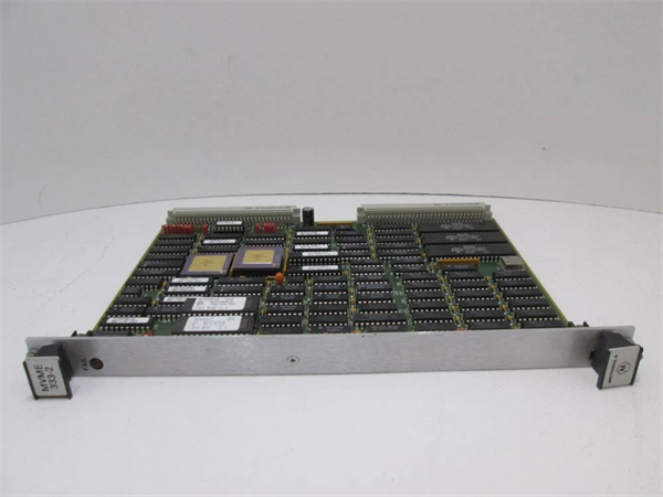
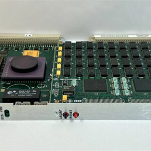
MOTOROLA MVME333-2
Product Introduction
The Motorola MVME709-1 is a specialized VMEbus communication interface module, engineered to combine robust RS-485/RS-422 serial communication with fiber-optic connectivity—filling the gap between standard serial modules (e.g., MVME333-2) and dedicated fiber-optic gateways. As a 3U VME form factor device, it is designed for industrial systems that require long-distance, noise-immune data transmission (e.g., across factory campuses or harsh industrial zones), while retaining compatibility with legacy serial devices and adding local digital I/O for basic control tasks.
A defining strength of the MVME709-1 is its seamless integration with the Motorola VME ecosystem. When paired with a host SBC like the MVME5500, it leverages the VMEbus to receive configuration commands (e.g., serial baud rate, fiber data rate, digital I/O direction) and transmit multi-medium data—such as RS-485 sensor readings from local equipment, fiber-optic data from remote control cabinets, and digital I/O states from safety interlocks. It draws stable power from modules like the FAB 0340-1049 (via VME backplane) or 01-W3324F (for auxiliary power), while its -20°C–70°C temperature range ensures reliability in extreme environments—from freezing outdoor utility cabinets to hot steel mill control rooms.
Whether deployed in large-scale manufacturing campuses、utility grid substations, or mining operations, the MVME709-1 enables resilient long-distance communication. Its fiber-optic ports eliminate EMI interference (common in industrial settings) and extend transmission distance to 2 km, while RS-485 ports retain compatibility with thousands of legacy devices—making it a critical component for legacy VME systems requiring both connectivity flexibility and environmental robustness.
Core Advantages and Technical Highlights
Dual-Medium Communication (RS-485 + Fiber-Optic) for Flexible Connectivity
The MVME709-1’s combination of 2x RS-485/RS-422 ports and 2x fiber-optic ports eliminates the need for separate serial modules and fiber-optic gateways—reducing VME chassis slot usage by up to 50%. For example, in a large automotive manufacturing campus with two factories (1.5 km apart), the module can: 1) use 2x RS-485 ports to connect local MVME172PA-644SE analog modules (monitoring assembly line sensors), 2) use 1x fiber-optic port to transmit aggregated data to the central control cabinet (avoiding EMI from factory motors), 3) use the remaining fiber-optic port for redundant communication, and 4) use 8x digital I/O channels to control local alarm lights. This dual-medium design simplifies campus-wide connectivity, reduces wiring costs (fiber-optic cables are lighter and more durable than copper for long distances), and ensures data integrity in high-noise environments.
Fiber-Optic Communication for EMI Immunity and Long Distance
The MVME709-1’s fiber-optic ports (multimode, 850 nm) provide immunity to electromagnetic interference (EMI)—a critical advantage over copper-based communication (e.g., RS-485) in industrial settings with heavy machinery, welders, or high-voltage equipment. Unlike copper cables, which pick up EMI and suffer signal degradation, fiber-optic cables transmit light signals, ensuring data integrity even near 480 VAC motor controllers or 110 kV power lines. In a utility grid substation, for instance, the module’s fiber-optic ports transmit MVME172PA-644SE voltage/current data across 2 km to a central SCADA system without corruption, while RS-485 ports connect local temperature sensors—avoiding the need for expensive shielded copper cables. The 2 km transmission distance also eliminates the need for repeaters in medium-scale campus deployments, reducing system complexity and maintenance costs.
Extended Environmental Tolerance for Harsh Conditions
With an operating temperature range of -20°C–70°C, the MVME709-1 operates reliably in environments that challenge standard communication modules (e.g., MVME335’s -10°C–70°C). In an outdoor utility substation where winter temperatures drop to -18°C, the module’s low-temperature tolerance ensures fiber-optic communication with remote transformers remains active, while its high-temperature resilience (70°C) withstands summer heat in uncooled cabinets. The passive cooling design avoids fan-related failures in dusty environments (e.g., cement plants), and the ST fiber-optic connectors (with dust caps) prevent contamination—extending the module’s lifespan in harsh industrial settings.
Robust Protection and Diagnostic Features for Reliability
The MVME709-1 includes multiple protection and diagnostic features to ensure long-term reliability: 1) 2 kV ESD surge protection on serial and fiber-optic ports safeguards against maintenance-induced static discharge, 2) fiber-optic link loss detection (via LED indicators and VMEbus interrupts) alerts the MVME5500 SBC to broken or disconnected cables, 3) overcurrent protection on digital I/O channels prevents damage from short circuits. For example, in a mining operation where dust and vibration are prevalent, the module’s link loss detection quickly identifies a damaged fiber-optic cable (before it causes unplanned downtime), while surge protection prevents port damage from static discharge when technicians replace sensors. These features reduce maintenance time by 40% compared to modules without built-in diagnostics.
Typical Application Scenarios
Manufacturing Campus Wide Control
In a 2 km-wide electronics manufacturing campus, the MVME709-1 (paired with MVME5500 SBC) connects three distributed control cabinets: 1) in Cabinet A (semiconductor cleanroom), 2x RS-485 ports link to MVME-204A728-1 modules (monitoring wafer processing sensors), 2) 1x fiber-optic port transmits data to Cabinet B (assembly line control) 1 km away, 3) the second fiber-optic port connects to Cabinet C (central SCADA) 2 km away, and 4) 8x digital I/O channels control cleanroom access lights. The fiber-optic links avoid EMI from campus-wide conveyor motors, while RS-485 ports handle local connectivity—ensuring real-time synchronization of wafer processing and assembly steps, critical for meeting production deadlines.
Utility Grid Substation Monitoring
In a high-voltage power grid substation, the MVME709-1 (paired with MVME2434 SBC) manages remote data collection: 1) 2x RS-485 ports connect to MVME172PA-644SE modules (sampling transformer voltage/current), 2) 2x fiber-optic ports transmit data to a remote control center 1.5 km away (avoiding EMI from 110 kV power lines), 3) 4x digital input channels monitor substation door interlocks, and 4) 4x digital output channels activate emergency shutdown relays. The module’s -20°C tolerance withstands winter subzero temperatures, while fiber-optic communication ensures data integrity during lightning storms (a common cause of copper cable signal loss in substations).
Mining Operation Remote Control
In an underground mining operation with two shafts (1 km apart), the MVME709-1 (paired with MVME172-263/260 SBC) enables cross-shaft communication: 1) 2x RS-485 ports connect to local gas detectors and MVME335 modules (monitoring mine conditions), 2) 1x fiber-optic port transmits safety data to the surface control room (fiber-optic cables are immune to mine electrical interference), 3) the second fiber-optic port provides redundant communication, and 4) 8x digital I/O channels control shaft elevator emergency stops. The module’s passive cooling design avoids fan failures in dusty mine air, while surge protection prevents damage from electrical equipment used in mining—ensuring 24/7 safety monitoring.
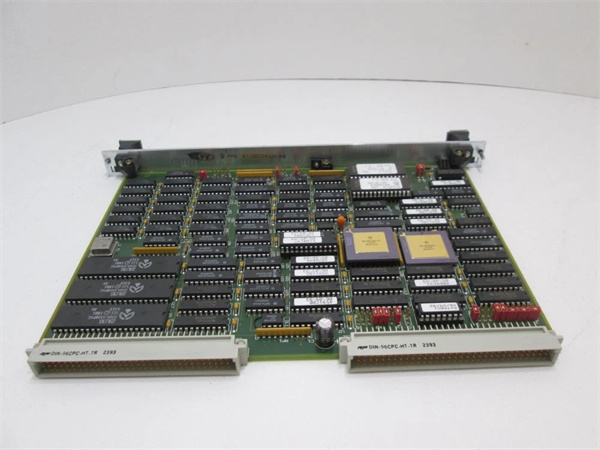
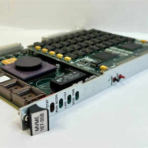
MOTOROLA MVME333-2
Related Model Recommendations
Motorola MVME5500: VME SBC. Host controller for MVME709-1; configures serial/fiber ports and digital I/O, processes multi-medium data, and executes control logic—critical for leveraging the module’s dual-communication functionality.
Motorola FAB 0340-1049: Power supply module. Primary power source for MVME709-1; delivers stable +5 VDC (1.5 A max) and +12 VDC to support the module’s serial/fiber and digital I/O circuits.
Motorola 01-W3324F: Power distribution terminal block. Supplies auxiliary power to MVME709-1 (if VME backplane power is insufficient) and distributes 24 VDC to connected digital I/O devices (e.g., alarms, interlocks).
Motorola FLN4234A: Communication expansion module. Complements MVME709-1 in large systems; the FLN4234A’s 4x Ethernet ports extend the MVME709-1’s fiber/serial data to cloud-based monitoring platforms.
Motorola MVME172PA-644SE: High-precision analog I/O module. Key data source for MVME709-1; transmits high-precision sensor data to the module for long-distance transmission via fiber-optic ports.
Corning 62.5/125 µm Multimode Fiber: Fiber-optic cable (compatible with MVME709-1). Extends the module’s fiber-optic transmission to 2 km, ideal for campus-wide or remote site connectivity.
Emerson RSTi-EP Fiber/Ethernet Gateway: Modern communication module. Replacement for MVME709-1 in systems migrating to Ethernet; offers fiber-optic + Gigabit Ethernet connectivity with compatibility with MVME5500 via protocol conversion.
Installation, Commissioning and Maintenance Instructions
Installation Preparation
Before installing MVME709-1, power off the VME chassis and disconnect the FAB 0340-1049 and 01-W3324F power supplies to prevent electrical shock. Verify the chassis has an available 3U VME slot and that the VME backplane supports 16-bit slave modules. Use an anti-static wristband and mat to protect the module’s serial/fiber components from ESD damage. Gather tools: Phillips-head screwdriver (for chassis mounting), twisted-pair cables (RS-485/RS-422, 22–18 AWG), multimode fiber-optic cables (62.5/125 µm, with ST connectors), torque wrench (0.5–0.8 N·m for terminals), and a fiber-optic power meter (to test link loss). Avoid installing near high-voltage equipment (e.g., transformers) or heat sources (e.g., power resistors) to prevent EMI or thermal damage.
Commissioning and Maintenance
For commissioning, insert the MVME709-1 into the VME slot and secure it. Wire RS-485 devices to the serial ports (A/B/GND) and fiber-optic devices to the ST connectors (ensure proper alignment to avoid signal loss). Connect digital I/O devices to the terminals, matching TTL/CMOS voltage levels. Power on the FAB 0340-1049 and 01-W3324F, then check the module’s LEDs: green “POWER” confirms voltage; serial “TX/RX” (blinking) indicates data transmission; fiber “LINK” (solid green) confirms a valid connection; digital I/O “HIGH” (green)/“ACTIVE” (red) confirms state. Use the MVME5500’s configuration software to set serial parameters (baud rate, parity) and fiber data rate (up to 10 Mbps). Test communication: send RS-485 test data to a local sensor and verify fiber-optic transmission to a remote cabinet (use a power meter to confirm link loss <18 dBm).
For maintenance: Inspect RS-485 and fiber-optic connections monthly—tighten loose terminals, clean ST connectors with lint-free wipes (use isopropyl alcohol for dirt), and replace damaged cables. Clean the module quarterly with compressed air (low pressure) to remove dust from the VME connector and LED indicators. Test fiber-optic link loss semi-annually (using a power meter) to ensure it remains within the -18 dBm limit. If a fiber port fails, reconfigure a serial port for critical local devices; if digital I/O malfunctions, isolate the issue with a bench power supply. When upgrading, replicate the module’s communication parameters to avoid disrupting long-distance data transmission—use EEPROM backup to transfer settings to a new unit.
Service and Guarantee Commitment
Though Motorola MVME709-1 is obsolete, we offer a 90-day warranty on all refurbished units—covering defects in serial/fiber-optic port functionality, digital I/O performance, surge protection, and LED indicators. Each refurbished module undergoes rigorous testing: 24-hour serial data transfer (115.2 kbps, zero packet loss over 1200 m), fiber-optic link validation (2 km, link loss <18 dBm), digital I/O cycling (overcurrent protection test), and ESD surge testing (2 kV). This guarantees compliance with original industrial-grade communication standards.
Our technical support team (24/7 availability) provides guidance on MVME709-1 installation、fiber-optic link design (e.g., cable routing, connector termination), and integration with VME SBCs like the MVME5500 or MVME2434. We offer customized maintenance plans