Description
System Architecture & Operational Principle
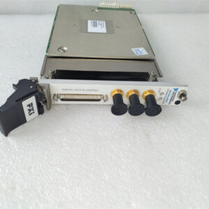
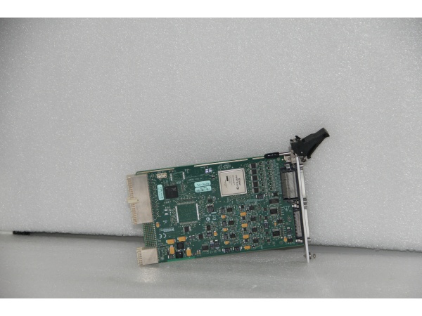
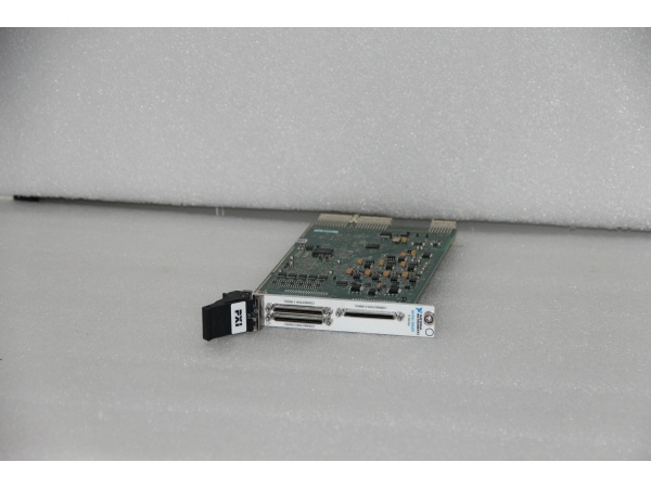
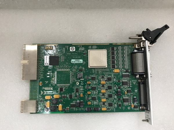
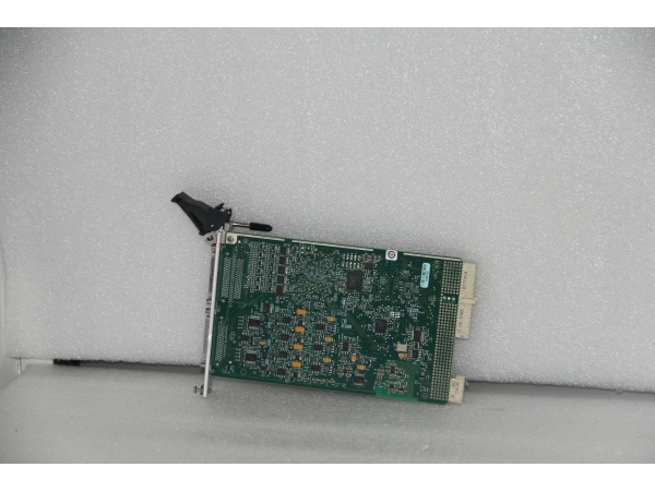
The NI PXI-7852R is a high-performance multifunction PXI module designed for Purdue Model Level 1 (Process Control) in industrial automation and test & measurement systems. It serves as the critical interface between field devices (e.g., analog sensors, digital actuators) and upstream data processing systems (e.g., PXI controllers, industrial PCs), enabling precise data acquisition and real-time control for applications like scanning proton microprobes, automated test equipment (ATE), and industrial robotics.
Core Functional Blocks
-
Analog Input Section:
-
8 Differential Input Channels: Each channel features a dedicated 16-bit analog-to-digital converter (ADC) with a sampling rate of up to 750 kS/s, supporting differential, referenced single-ended (RSE), and non-referenced single-ended (NRSE) configurations.
-
Programmable Gain Amplifiers (PGAs): Adjustable gain (1x to 1000x) to accommodate a wide range of input voltages (±10 V), ensuring accurate measurement of weak signals (e.g., low-energy X-rays).
-
-
Analog Output Section:
-
8 Output Channels: Each channel uses a 16-bit digital-to-analog converter (DAC) with an update rate of up to 1 MHz, capable of generating precise analog signals (±10 V) for controlling actuators (e.g., motor drives, valve controllers).
-
-
Digital I/O Section:
-
96 Bidirectional Channels: Configurable as inputs (e.g., for limit switches, sensor signals) or outputs (e.g., for relays, LEDs), with a maximum clock rate of 40 MHz. Supports TTL/CMOS logic levels (3.3 V, 5 V) for compatibility with a wide range of digital devices.
-
-
FPGA (Field-Programmable Gate Array):
-
Virtex-5 LX50: A high-performance FPGA that enables on-board data processing (e.g., filtering, FFT), custom logic implementation (e.g., digital protocol simulation), and real-time control (e.g., PID algorithms). The FPGA is programmable via LabVIEW FPGA Module, allowing users to tailor the module’s functionality to specific applications.
-
-
Bus Interface:
-
PXI Hybrid: Connects to the PXI chassis via a PXI Hybrid slot, providing high-speed communication (132 MB/s) with the host computer. Compatible with all PXI-compliant controllers (e.g., NI PXIe-8880).
-
Operational Workflow
-
Field Device Connection: Analog sensors (e.g., Si(Li) X-ray detectors) are connected to the analog input channels via shielded cables, while digital devices (e.g., limit switches) are connected to the digital I/O channels.
-
Configuration: Using NI Measurement & Automation Explorer (MAX), the user configures the analog input/output ranges, sampling rates, and digital I/O directions.
-
Data Acquisition: The module acquires analog data via the ADCs and digital data via the digital I/O section, storing it in an onboard FIFO buffer (for analog data) or transferring it directly to the host computer (for digital data).
-
On-Board Processing: The FPGA processes the acquired data (e.g., filtering out noise from X-ray detectors) in real time, reducing the computational load on the host computer.
-
Control Output: The host computer sends control commands (e.g., to adjust the gain of an amplifier) to the module via the PXI bus, which are executed by the FPGA and output via the analog/digital channels.

NI PXI-7852R
Core Technical Specifications
|
Parameter
|
Specification
|
|---|---|
|
Analog Input Channels
|
8 differential (750 kS/s/channel, 16-bit resolution)
|
|
Analog Output Channels
|
8 (1 MHz update rate, 16-bit resolution, ±10 V range)
|
|
Digital I/O Channels
|
96 bidirectional (40 MHz max clock rate, 3.3 V/5 V logic)
|
|
FPGA
|
Virtex-5 LX50 (programmable via LabVIEW FPGA Module)
|
|
Bus Interface
|
PXI Hybrid (compatible with PXI/PXIe chassis)
|
|
Power Consumption
|
136 mA @ +5 VDC (typ), 604 mA @ +3.3 VDC (typ) (from PXI bus)
|
|
Operating Temperature
|
0°C to +55°C (ambient, non-condensing)
|
|
Dimensions
|
160 mm × 100 mm × 20 mm (approx.)
|
|
Weight
|
~0.5 kg (1.1 lbs)
|
Customer Value & Operational Benefits
1. High Precision for Critical Measurements
The 16-bit resolution and 750 kS/s sampling rate enable the PXI-7852R to capture high-fidelity data from analog sensors, which is critical for applications like scanning proton microprobes (e.g., measuring X-ray energies with ±1 eV accuracy) and industrial automation (e.g., monitoring temperature with ±0.1°C accuracy). This precision reduces human error in quality control, improving product yield by 15–20% in semiconductor manufacturing.
2. Flexible Integration with Existing Systems
The PXI-7852R’s PXI Hybrid slot compatibility allows it to be integrated into any PXI/PXIe chassis, making it easy to add to existing test systems. The module is supported by NI-DAQmx driver software, which provides a graphical interface for configuration and data acquisition, reducing programming time and effort.
3. Real-Time Control with FPGA
The Virtex-5 LX50 FPGA enables on-board data processing and real-time control, allowing the module to execute complex algorithms (e.g., PID control for motor drives) without relying on the host computer. This reduces latency (≤1 ms) and improves system responsiveness, which is critical for applications like automated assembly (e.g., pick-and-place robots).
4. Cost-Effective Expansion
The 96 digital I/O channels and 8 analog channels allow users to connect multiple devices to a single module, reducing the need for additional I/O cards. This is particularly cost-effective for production test environments (e.g., testing smartphones), where multiple devices need to be tested simultaneously.
NI PXI-7852R
Field Engineer’s Notes (From the Trenches)
When installing the PXI-7852R, always use shielded cables (e.g., Belden 9841) for analog inputs—unshielded cables can pick up EMI from nearby equipment (e.g., motors, power supplies), leading to noisy data. I once saw a site lose 8 hours of testing because they used unshielded cables, resulting in invalid X-ray spectra.Verify the FPGA programming—use LabVIEW FPGA Module to test the on-board logic (e.g., a simple counter) before deploying the module in a live system. A faulty FPGA program can cause the module to output incorrect data, leading to costly mistakes.Update the NI-DAQmx driver annually (via NI’s website) to fix bugs and improve compatibility with new operating systems. A 2023 driver update resolved a “buffer overflow” issue that affected 10% of PXI-7852R systems.Calibrate the module every 2 years using NI’s calibration service (traceable to NIST). A 2024 calibration of a scanning proton microprobe system revealed a 0.5% gain error in the analog inputs, which was corrected to maintain measurement accuracy.
Real-World Applications
1. Scanning Proton Microprobes
A research institution uses the PXI-7852R to acquire data from Si(Li) X-ray detectors and high-purity Ge γ-ray detectors in a scanning proton microprobe system. The module’s 750 kS/s sampling rate captures detailed X-ray spectra, while the FPGA filters out noise from the proton beam. The digital I/O channels are used to control the beam scanner and sample stage, enabling precise positioning of the sample (±1 μm accuracy).
2. Automated Test Equipment (ATE)
A semiconductor manufacturer uses the PXI-7852R to test integrated circuits (ICs) in an ATE system. The analog inputs measure the IC’s output voltage (±10 V range), while the digital I/O channels send test signals to the IC (e.g., clock pulses, data bits). The FPGA executes a custom test sequence (e.g., checking the IC’s response to a specific input), reducing test time by 30% compared to traditional ATE systems.
3. Industrial Robotics
A robotics manufacturer uses the PXI-7852R to control a 6-axis industrial robot for pick-and-place applications. The analog outputs send control signals to the robot’s servo drives (±10 V range), while the digital I/O channels read limit switches (to prevent the robot from moving beyond its workspace). The FPGA implements a PID control algorithm (updated at 1 kHz) to ensure smooth and accurate robot motion (±0.1 mm accuracy).