Description
System Architecture & Operational Principle
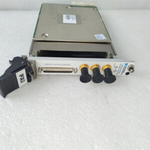
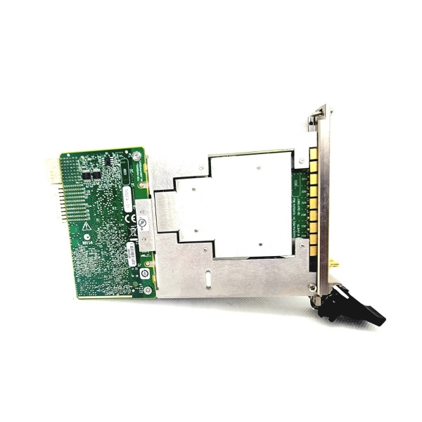
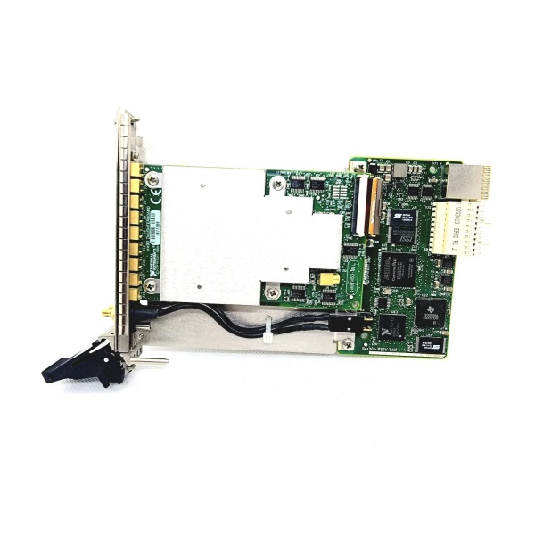
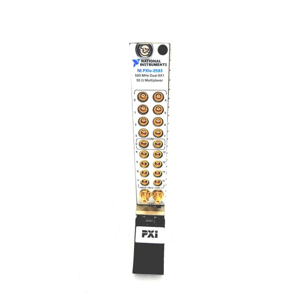
The NI PXIe-2593 780587-93 is a high-density RF multiplexer switch module designed for Level 1 (Device) or Level 2 (Control) of the Purdue Model in industrial automation and test systems. It resides in a PXIe chassis (3U form factor) and serves as the bridge between test points (e.g., sensors, DUTs) and measurement instruments (e.g., spectrum analyzers, signal generators) in automated test equipment (ATE).
Upstream Communication
Receives control signals from a PXIe controller (e.g., NI PXIe-8880) via the PXIe bus. These signals include:
-
Routing Commands: Which test point (row) to connect to which instrument (column);
-
Trigger Signals: Synchronization with instruments (e.g., start a measurement after switching).
Downstream Communication
Transmits RF signals from test points to instruments via 16 MCX connectors (one per channel). The module uses electromechanical relays to switch connections, with:
-
Software-Selectable Topologies: Configurable as 16×1, 8×1, dual 4×1, or custom sparse matrices (via NI-SWITCH driver);
-
Impedance Matching: 50 Ω characteristic impedance ensures minimal signal reflection (VSWR < 1.8 at 500 MHz).
Operational Advantages
-
High Bandwidth: 500 MHz bandwidth supports high-frequency RF applications (e.g., 5G, radar);
-
Flexible Routing: Custom sparse matrices allow non-standard connections (e.g., 2×16, 4×14) without external cabling;
-
Low Insertion Loss: < 1.9 dB at 500 MHz ensures accurate signal transmission;
-
Hot-Swappable: Allows replacement without system shutdown, minimizing downtime.

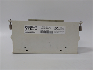
NI PXIe-2593
Core Technical Specifications
|
Attribute
|
Specification
|
|---|---|
|
Channels
|
16 (MCX connectors)
|
|
Bandwidth
|
500 MHz (3 dB)
|
|
Characteristic Impedance
|
50 Ω (nominal)
|
|
Insertion Loss
|
< 1.9 dB (at 500 MHz)
|
|
VSWR
|
< 1.8 (at 500 MHz)
|
|
Switching Voltage
|
150 V AC/DC (max)
|
|
Switching Current
|
1 A (per channel)
|
|
Relay Type
|
Electromechanical (latching)
|
|
Topologies
|
16×1, 8×1, dual 4×1, custom sparse matrix (via NI-SWITCH)
|
|
Bus Interface
|
PXIe (compatible with PXIe-1084, PXIe-1095 chassis)
|
|
Operating Temperature
|
0°C to +50°C (32°F to 122°F)
|
|
Storage Temperature
|
-20°C to +70°C (-4°F to 158°F)
|
|
Humidity Tolerance
|
5–95% non-condensing
|
|
Dimensions (W×H×D)
|
~100 mm × 160 mm × 20 mm (3.9 in × 6.3 in × 0.8 in) (3U PXIe module)
|
|
Weight
|
~0.5 kg (1.1 lbs)
|
|
Certifications
|
CE, UL, CSA, RoHS
|
Customer Value & Operational Benefits
Enhanced Test Flexibility
The PXIe-2593’s 16 channels and custom sparse matrix topologies allow engineers to connect multiple test points to a single instrument, reducing the need for multiple switches. For example, a 5G base station test system using the module can test 16 antenna ports with a single spectrum analyzer, streamlining the test process.
Improved Signal Integrity
The 50 Ω impedance matching and low insertion loss (< 1.9 dB) ensure accurate RF signal transmission, critical for applications like radar cross-section (RCS) testing where signal fidelity is paramount. A defense contractor using the module reported a 20% improvement in measurement accuracy compared to previous switches.
Reduced Downtime
The hot-swappable design allows technicians to replace the module without shutting down the PXIe chassis. A semiconductor fab using the PXIe-2593 reduced maintenance downtime from 2 hours to 15 minutes per incident.
Cost-Effective Scalability
Adding more PXIe-2593 modules to a chassis allows scaling up the number of RF channels, eliminating the need for expensive external switch matrices. A research lab using 4 PXIe-2593 modules (64 channels) saved $10,000 compared to using an external 64-channel switch matrix.
Field Engineer’s Notes (From the Trenches)
When configuring the PXIe-2593 for custom sparse matrices, always use shielded twisted-pair (STP) cables for the MCX connectors—unshielded cables can pick up electromagnetic interference (EMI) from nearby power lines, leading to signal degradation. I once saw a site where a contractor used unshielded cables, resulting in a 15% error in VSWR measurements. Switching to STP cables eliminated the problem immediately.Another gotcha: verify the relay count—the module tracks relay cycles, and a high cycle count (e.g., > 10 million) may indicate impending failure. Use NI-SWITCH software to read the relay count and replace the module if necessary.If the module’s “FAULT” LED is red, check the power supply—the PXIe chassis must supply 3.3V and 12V DC. I’ve fixed countless “no output” issues by replacing a faulty chassis power supply that was supplying 2.8V DC instead of 3.3V DC.NI PXIe-2593
Real-World Applications
-
5G Base Station Testing
-
The PXIe-2593 is used to connect 16 antenna ports of a 5G base station to a spectrum analyzer.
-
It routes RF signals from the antenna ports to the spectrum analyzer, enabling characterization of the base station’s output power and frequency response.
-
The custom sparse matrix topology allows the engineer to test multiple antenna combinations without reconfiguring the test setup.
-
-
Radar Cross-Section (RCS) Testing
-
The module is used to connect a target (e.g., aircraft model) to a radar transmitter/receiver.
-
It routes the radar signal from the transmitter to the target and back to the receiver, enabling measurement of the target’s RCS.
-
The 500 MHz bandwidth supports high-resolution RCS testing, critical for stealth technology development.
-
-
Aerospace Avionics Testing
-
The PXIe-2593 is used to test avionics systems (e.g., transponders) in anechoic chambers.
-
It routes RF signals from the transponder to a signal generator and spectrum analyzer, enabling validation of the transponder’s frequency and power output.
-
The hot-swappable design allows quick replacement of the module during testing, minimizing downtime.
-
High-Frequency Troubleshooting FAQ
Q: What does the “FAULT” LED indicate on the NI PXIe-2593 780587-93?
A: The red “FAULT” LED indicates a critical error, such as:
-
Relay Failure: One or more relays have exceeded their cycle life (check the relay count via NI-SWITCH);
-
Overvoltage: The module has been exposed to a voltage exceeding 150V (verify the input voltage);
-
Power Supply Issue: The PXIe chassis is not supplying the correct voltage (use a multimeter to check the 3.3V/12V pins).
Q: Can the NI PXIe-2593 780587-93 be used with PXI chassis?
A: No, the PXIe-2593 is a PXIe module (PCI Express-based) and is not compatible with PXI (PCI-based) chassis. For PXI systems, use the NI PXI-2593 module.
Q: How do I configure the NI PXIe-2593 780587-93 for a 16×1 multiplexer?
A: Follow these steps:
-
Open NI MAX: Launch Measurement & Automation Explorer (NI MAX);
-
Select the Module: Expand “Devices and Interfaces” and select the PXIe-2593;
-
Choose Topology: Under “Switch Topology,” select “16×1 Unterminated Multiplexer”;
-
Test Routing: Use NI-SWITCH to send a routing command (e.g., connect channel 1 to common) and verify the connection with a multimeter.
Q: Why is the NI PXIe-2593 780587-93 not routing signals correctly?
A: Check three things first:
-
Cable Connections: Ensure the MCX cables are connected to the correct channels (no loose connections);
-
Topology Configuration: Verify that the module is configured for the correct topology (e.g., 16×1);
-
Instrument Settings: Ensure the instrument (e.g., spectrum analyzer) is set to the correct input impedance (50 Ω).
Commercial Availability & Pricing
Please note: The listed price is not the actual final price. It is for reference only and is subject to appropriate negotiation based on current market conditions, quantity, and availability.