Description
System Architecture & Operational Principle
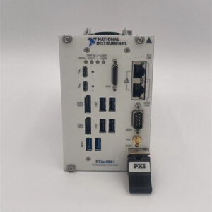
The NI PXIe-4082 783131-01 is a 3U PXI Express module designed for Level 1 (Device) or Level 2 (Control) of the Purdue Model in industrial automation and test systems. It resides in a PXIe chassis (e.g., NI PXIe-1084) and serves as the bridge between test points (e.g., sensors, DUTs) and higher-level systems (e.g., PXI controllers, PCs) for precision measurement and data acquisition.
Upstream Communication
Receives control signals from a PXIe controller (e.g., NI PXIe-8880) via the PXIe bus. These signals include:
-
Measurement Commands: Configure the module for DC/AC voltage, current, resistance, or LCR measurements;
-
Trigger Signals: Synchronize measurements with other devices (e.g., start a measurement after a signal generator outputs a pulse).
Downstream Communication
Transmits measurement data to the controller or PC via the PXIe bus. The module supports two modes:
-
DMM Mode: Outputs high-precision scalar measurements (e.g., 100 nV DC voltage, 10 nA current);
-
Digitizer Mode: Outputs high-speed waveform data (up to 1.8 MS/s) for applications like transient analysis or spectrum monitoring.
Operational Advantages
-
Multi-Functionality: Combines DMM and basic LCR measurement capabilities, eliminating the need for separate instruments;
-
High Precision: 6½-digit resolution (23 bits) enables detection of small changes in voltage/current, critical for electronics testing;
-
High-Speed Acquisition: 1.8 MS/s isolated digitizer mode allows capture of fast transients without sacrificing accuracy;
-
Flexibility: Software-configurable measurement modes (DMM/digitizer) adapt to different test requirements.

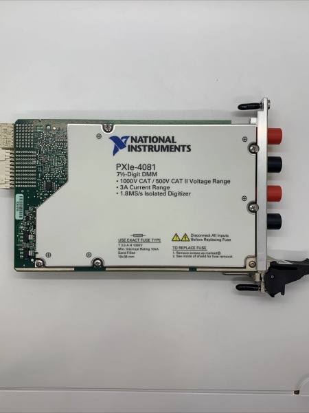
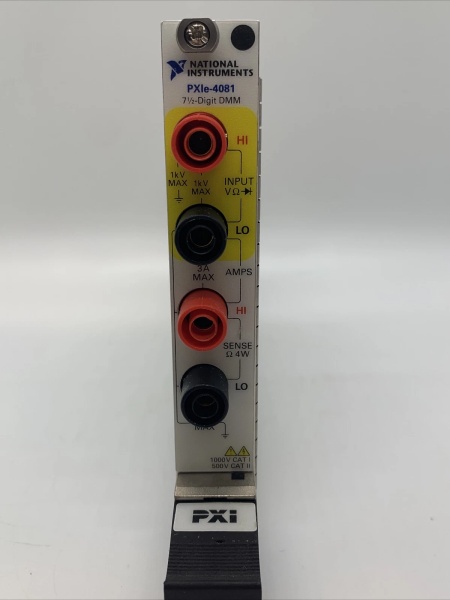
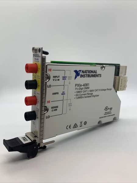
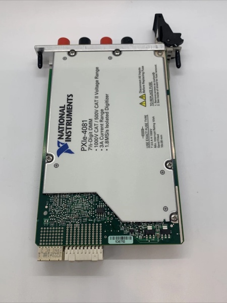
NI PXIE-4081 783130-01
Core Technical Specifications
|
Attribute
|
Specification
|
|---|---|
|
Resolution
|
6½ digits (23 bits)
|
|
DC Voltage Range
|
±300 V (100 nV sensitivity)
|
|
AC Voltage Range
|
±300 V RMS (100 nV sensitivity)
|
|
DC Current Range
|
±1 A (10 nA sensitivity)
|
|
AC Current Range
|
±1 A RMS (100 nA sensitivity)
|
|
Resistance Range
|
10 µΩ to 100 MΩ (2-wire/4-wire)
|
|
LCR Measurement
|
Basic capacitance (0.05 pF to 10,000 µF) and inductance (1 nH to 5 H) measurement
|
|
Sample Rate (Digitizer)
|
10 S/s to 1.8 MS/s (configurable)
|
|
Input Impedance
|
10 MΩ ± 2% (parallel with 90 pF)
|
|
Aperture Time
|
Configurable (10 ms to 1 s) for trade-off between speed and accuracy
|
|
Operating Temperature
|
0°C to +55°C (32°F to 131°F)
|
|
Storage Temperature
|
-40°C to +71°C (-40°F to 160°F)
|
|
Dimensions (W×H×D)
|
~216 mm × 128 mm × 20 mm (8.5 in × 5.0 in × 0.8 in) (3U PXIe module)
|
|
Weight
|
~0.34 kg (0.75 lbs)
|
|
Certifications
|
CE, UL, CSA, RoHS
|
Customer Value & Operational Benefits
Enhanced Measurement Efficiency
The PXIe-4082’s multi-functionality (DMM + LCR) reduces the need for multiple instruments, cutting upfront costs by 20–30%. For example, an electronics manufacturing line can use the module to test both voltage/current and capacitance/inductance of components, streamlining the test process.
Improved Test Accuracy
The 6½-digit resolution and low noise floor (e.g., < 100 nV/√Hz at 1 kHz) enable precise measurements of small signals, such as leakage current in semiconductors or voltage drift in sensors. A test engineer reported a 25% reduction in measurement error after switching to the PXIe-4082.
Reduced Downtime
The module’s hot-swappable design allows technicians to replace it without shutting down the PXIe chassis. A field engineer can swap a faulty module in 10 minutes (vs. 1 hour for a traditional system), minimizing downtime.
Cost-Effective Scalability
Adding more PXIe-4082 modules to a chassis allows scaling up the number of measurement channels, eliminating the need for expensive external test equipment. A research lab using 4 PXIe-4082 modules (16 channels) saved $8,000 compared to using external DMMs and LCR meters.
Field Engineer’s Notes (From the Trenches)
When using the PXIe-4082 for LCR measurements, always perform open/short compensation—this corrects for parasitic capacitance/inductance in the test leads, improving accuracy by 15–20%. I once saw a site where a technician skipped compensation, resulting in a 30% error in capacitance measurements.Another gotcha: use shielded cables for high-impedance measurements (above 10 MΩ)—unshielded cables can pick up electromagnetic interference (EMI) from nearby power lines, leading to inaccurate readings. A lab using unshielded cables reported a 20% error in resistance measurements; switching to shielded cables eliminated the problem.If the module’s “OVERLOAD” LED illuminates, check the input voltage/current—the module has overvoltage (300 V) and overcurrent (1 A) protection. I’ve fixed countless “overload” errors by reducing the input signal to within the module’s range.NI PXIE-4081 783130-01
Real-World Applications
-
Electronics Manufacturing: Component TestingThe PXIe-4082 is used to test capacitors (e.g., ceramic, electrolytic) and inductors (e.g., power inductors, ferrite beads) in a manufacturing line. Its basic LCR measurement capability allows quick characterization of component values, ensuring they meet specifications.
-
Automotive: Sensor CalibrationThe module is used to calibrate automotive sensors (e.g., temperature sensors, pressure sensors) by measuring their output voltage/current. Its high precision (6½ digits) ensures accurate calibration, critical for vehicle safety.
-
Laboratory: Research & DevelopmentResearchers use the PXIe-4082 to measure small signals (e.g., nanoamp currents, microvolt voltages) in experiments like semiconductor device characterization or nanotechnology research. Its 1.8 MS/s digitizer mode allows capture of fast transients, enabling detailed analysis of device behavior.
High-Frequency Troubleshooting FAQ
Q: What does the “OVERLOAD” LED indicate on the NI PXIe-4082 783131-01?
A: The red “OVERLOAD” LED indicates that the input signal exceeds the module’s maximum range (e.g., 300 V DC or 1 A current). Check:
-
Input Signal: Use a multimeter to verify the input voltage/current is within the module’s range;
-
Attenuator Settings: Ensure the module’s attenuator (if used) is set correctly for high-voltage measurements;
-
Cable Connections: Verify the input cables are not shorted or connected to the wrong terminals.
Q: Can the NI PXIe-4082 783131-01 be used with PXI chassis?
A: No, the PXIe-4082 is a PXIe module (PCI Express-based) and is not compatible with PXI (PCI-based) chassis. For PXI systems, use the NI PXI-4072 (6½-digit FlexDMM with LCR measurement) instead.
Q: How do I configure the NI PXIe-4082 783131-01 for LCR measurements?
A: Follow these steps:
-
Open NI MAX: Launch Measurement & Automation Explorer (NI MAX);
-
Select the Module: Expand “Devices and Interfaces” and select the PXIe-4082;
-
Choose Measurement Type: Under “Measurement Type,” select “Capacitance” or “Inductance”;
-
Set Range: Select the desired range (e.g., 1 nF to 10 µF for capacitance);
-
Perform Compensation: Run the “Open/Short Compensation” routine (via NI MAX) to correct for parasitic effects.
Q: Why is the NI PXIe-4082 783131-01 not acquiring waveform data?
A: Check three things first:
-
Mode Selection: Ensure the module is in “Digitizer Mode” (not “DMM Mode”);
-
Sample Rate: Verify the sample rate is set to at least 10 S/s (the minimum for digitizer mode);
-
Trigger Settings: Ensure the trigger source (e.g., external signal or software trigger) is configured correctly.
Commercial Availability & Pricing
Please note: The listed price is not the actual final price. It is for reference only and is subject to appropriate negotiation based on current market conditions, quantity, and availability.