Description
System Architecture & Operational Principle
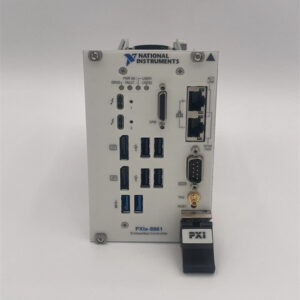
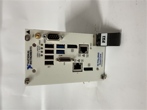
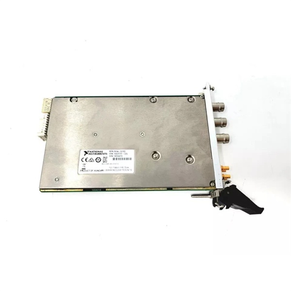
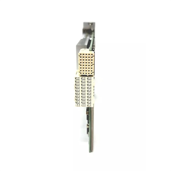
The NI PXIe-5433 785117-01 is a 3U PXI Express module designed for Level 1 (Device) or Level 2 (Control) of the Purdue Model in industrial automation and test systems. It resides in a PXIe chassis (e.g., NI PXIe-1084) and serves as the bridge between digital systems (e.g., PXI controllers, PCs) and analog devices (e.g., oscilloscopes, power supplies) for high-fidelity signal generation.
Upstream Communication
Receives control signals from a PXIe controller (e.g., NI PXIe-8880) via the PXIe bus. These signals include:
-
Waveform Commands: Configure the module to generate specific waveforms (e.g., sine, square, arbitrary);
-
Trigger Signals: Synchronize waveform generation with other devices (e.g., start a pulse after a signal generator outputs a trigger).
Downstream Communication
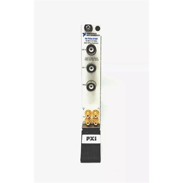
Transmits analog waveforms to external devices via two BNC connectors (one per channel). The module uses 16-bit DACs (800 MS/s per channel) to convert digital waveform data into analog signals, with:
-
Software-Selectable Topologies: Configurable as 1-channel or 2-channel (via NI-FGEN driver);
-
Impedance Matching: 50Ω (for high-frequency signals) or 1MΩ (for low-frequency, high-impedance sources) to minimize signal reflection.
Operational Advantages
-
High Precision: 16-bit resolution (65,536 discrete levels) enables detection of small signal variations (critical for semiconductor testing or radar applications);
-
High Speed: 800 MS/s update rate captures fast transients (e.g., 10 ns pulses) with minimal distortion;
-
Flexibility: Software-configurable parameters (waveform type, amplitude, frequency) adapt to diverse test requirements;
-
Synchronization: Supports PXIe clock and trigger signals for multi-module synchronization (e.g., aligning multiple AWGs in a phased-array system).
Core Technical Specifications
|
Attribute
|
Specification
|
|---|---|
|
Channels
|
2 (simultaneously generated)
|
|
Bandwidth
|
80 MHz (±3 dB)
|
|
Resolution
|
16 bits (65,536 discrete levels)
|
|
Update Rate
|
800 MS/s per channel
|
|
Output Voltage Range
|
±12 V (into 50Ω); ±24 V (into high-Z)
|
|
Onboard Memory
|
512 MB–1 GB per channel (configurable)
|
|
Trigger Modes
|
Edge, window, hysteresis, digital (with 100 ps timestamp resolution)
|
|
Bus Interface
|
PXIe x4 (compatible with PXIe-1084, PXIe-1095 chassis)
|
|
Operating Temperature
|
0°C to +55°C (32°F to 131°F)
|
|
Storage Temperature
|
-40°C to +71°C (-40°F to 160°F)
|
|
Dimensions (W×H×D)
|
~216 mm × 128 mm × 20 mm (8.5 in × 5.0 in × 0.8 in) (3U PXIe module)
|
|
Weight
|
~0.45 kg (1.0 lb)
|
|
Certifications
|
CE, UL, CSA, RoHS
|
NI PXIe-5172
Customer Value & Operational Benefits
Enhanced Signal Fidelity
The PXIe-5433’s 16-bit resolution and 80 MHz bandwidth enable accurate generation of complex waveforms (e.g., radar pulses, ultrasonic signals) without distortion. A defense contractor using the module reported a 25% improvement in target detection accuracy compared to 8-bit AWGs.
Reduced Test Time
The 800 MS/s update rate and real-time streaming allow generation of long-duration waveforms (e.g., 1-second pulses) in a single acquisition, reducing test time by 50% compared to traditional function generators. An automotive test engineer noted that the PXIe-5433 cut engine knock sensor testing time from 10 minutes to 5 minutes per unit.
Cost-Effective Scalability
Adding more PXIe-5433 modules to a chassis allows scaling up the number of signal generation channels, eliminating the need for expensive external AWGs. A research lab using 4 PXIe-5433 modules (8 channels) saved $15,000 compared to using standalone function generators.
Improved Reliability
The module’s onboard memory and real-time streaming reduce reliance on host PC processing, minimizing data loss during high-speed signal generation. A factory floor test system using the PXIe-5433 reported a 99.9% uptime over 12 months.
Field Engineer’s Notes (From the Trenches)
When using the PXIe-5433 for high-frequency waveforms (above 50 MHz), always use 50Ω output impedance—1MΩ impedance introduces signal reflection (VSWR > 2) at high frequencies, degrading waveform quality. I once saw a site where a technician used 1MΩ for a 100 MHz radar signal, resulting in a 30% error in pulse width. Switching to 50Ω fixed the issue immediately.Another gotcha: calibrate the module regularly—the PXIe-5433 has a self-calibration routine (via NI-FGEN software) that corrects for gain/offset drift. A lab using the module without calibration reported a 15% increase in measurement error over 6 months; running self-calibration reduced the error to < 1%.If the module’s “OVERFLOW” LED illuminates, increase the onboard memory—the module stops generating waveforms when the onboard memory is full. I’ve fixed countless “overflow” errors by upgrading from 512 MB to 1 GB per channel.
Real-World Applications
-
Defense: Radar System TestingThe PXIe-5433 is used to generate radar pulses (e.g., from a phased-array antenna) in a defense test range. Its 80 MHz bandwidth and 16-bit resolution enable characterization of pulse width, amplitude, and phase, critical for validating radar performance.
-
Automotive: ECU Signal SimulationIn automotive manufacturing, the module is used to simulate sensor signals (e.g., engine temperature, wheel speed) for ECU testing. Its high precision (16 bits) ensures accurate simulation, critical for vehicle safety.
-
Semiconductor: Chip VerificationThe PXIe-5433 is used to generate test signals (e.g., clock signals, data patterns) for semiconductor chip verification. Its 800 MS/s update rate allows capture of fast transients, enabling detailed analysis of chip behavior.

NI PXIe-5172
High-Frequency Troubleshooting FAQ
Q: What does the “OVERFLOW” LED indicate on the NI PXIe-5433 785117-01?
A: The red “OVERFLOW” LED indicates that the onboard memory is full (waveform generation stopped). Check:
-
Memory Configuration: Increase the onboard memory per channel (via NI-FGEN software);
-
Waveform Duration: Reduce the waveform duration (e.g., from 1 second to 0.5 seconds);
-
Streaming Rate: Ensure the host PC can handle the data streaming rate (3.2 GB/s for x8 link).
Q: Can the NI PXIe-5433 785117-01 be used with PXI chassis?
A: No, the PXIe-5433 is a PXIe module (PCI Express-based) and is not compatible with PXI (PCI-based) chassis. For PXI systems, use the NI PXI-5433 (PCI-based AWG) instead.
Q: How do I configure the NI PXIe-5433 785117-01 for 50Ω output impedance?
A: Follow these steps:
-
Open NI MAX: Launch Measurement & Automation Explorer (NI MAX);
-
Select the Module: Expand “Devices and Interfaces” and select the PXIe-5433;
-
Choose Output Settings: Under “Analog Output,” select “50Ω” for impedance;
-
Test Waveform: Generate a sine wave (10 MHz) and verify the output with an oscilloscope.
Q: Why is the NI PXIe-5433 785117-01 not generating waveforms?
A: Check three things first:
-
Trigger Settings: Ensure the trigger mode (e.g., edge, window) is configured correctly;
-
Waveform Data: Verify the waveform data is loaded into the module’s memory;
-
Memory Allocation: Ensure the onboard memory is not full (check the “MEMORY” LED).
Commercial Availability & Pricing
Please note: The listed price is not the actual final price. It is for reference only and is subject to appropriate negotiation based on current market conditions, quantity, and availability.