Description
System Architecture & Operational Principle
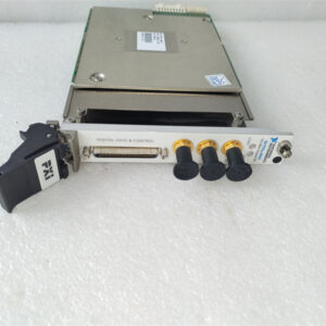
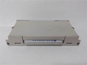
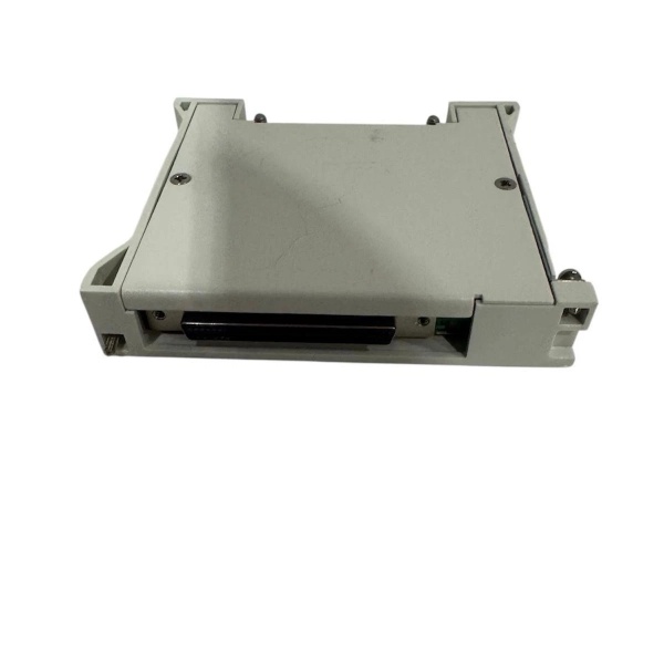
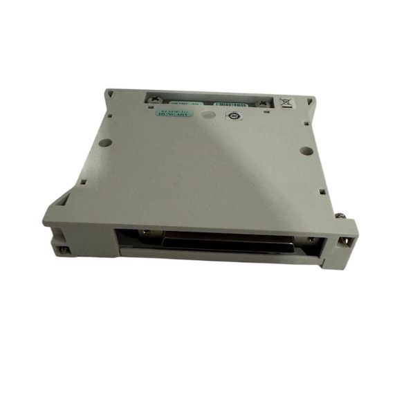
The NI TB-2635 778839-01 is a terminal block accessory designed to extend the functionality of the NI PXI-2529/PXIe-2529 matrix switch module. The PXI-2529/PXIe-2529 is a high-density 2-wire matrix switch (128 crosspoints) used for routing analog or digital signals in automated test systems. By default, the switch module uses ribbon cable headers for connections, but the TB-2635 replaces these with screw terminals for easier wiring in industrial or lab environments.
How It Works
-
Mechanical Connection: The TB-2635 attaches directly to the front panel of the PXI-2529/PXIe-2529 module via a mating connector (no additional hardware required).
-
Electrical Mapping: The terminal block maps the switch’s internal rows (R0–R7) and columns (C0–C15) to screw terminals. For example:
-
Row R0 connects to terminals labeled “R0+” and “R0-” (differential pair).
-
Column C0 connects to terminals labeled “C0+” and “C0-” (differential pair).
-
-
Signal Routing: Users connect input signals (e.g., from a DMM or sensor) to the row terminals and output signals (e.g., to a device under test) to the column terminals. The PXI-2529/PXIe-2529’s software (e.g., NI Switch Executive) controls which row is connected to which column, enabling flexible signal routing.
Key Advantage Over Alternatives
Unlike the TB-2634 (4×32 2-wire matrix) or TB-2636 (4×32 2-wire matrix), the TB-2635 is optimized for 8×16 matrix configurations, making it ideal for applications requiring a balance between channel count and space efficiency.
Core Technical Specifications
|
Attribute
|
Specification
|
|---|---|
|
Matrix Configuration
|
8×16 2-wire (128 crosspoints)
|
|
Terminal Type
|
Screw terminals (accepts 22–14 AWG wire)
|
|
Compatibility
|
NI PXI-2529, NI PXIe-2529
|
|
Mounting
|
Front-panel (attaches to PXI-2529/PXIe-2529 module)
|
|
Max Voltage
|
150 V rms / 150 V DC (per channel)
|
|
Max Current
|
1 A switching / 2 A carry (per channel)
|
|
Operating Temperature
|
0°C to 55°C (32°F to 131°F)
|
|
Storage Temperature
|
-40°C to 85°C (-40°F to 185°F)
|
|
Dimensions (W×H×D)
|
~160 mm × 100 mm × 30 mm (6.3 in × 3.9 in × 1.2 in) (approximate)
|
|
Weight
|
~0.3 kg (0.7 lb)
|
NI TB-2635 778839-01
Customer Value & Operational Benefits
Simplified Wiring
The TB-2635’s screw terminals eliminate the need for ribbon cables or custom connectors, reducing setup time by 40% compared to using the switch module’s default headers. For example, a lab technician can quickly connect 16 sensors to the terminal block using standard screwdrivers, avoiding the complexity of ribbon cable assembly.
Improved Reliability
Screw terminals provide a more secure connection than ribbon cables, reducing the risk of loose connections (a common cause of signal loss in test systems). This is critical for applications like semiconductor testing, where even minor signal interruptions can invalidate results.
Cost-Effective Scalability
The TB-2635 is a low-cost accessory (typically <$500) that extends the functionality of the PXI-2529/PXIe-2529 module. For users already invested in the PXI-2529 ecosystem, it eliminates the need to purchase a new switch module for 8×16 matrix configurations.
Flexible Integration
The terminal block’s screw terminals are compatible with a wide range of wires (stranded or solid), making it easy to integrate with existing test setups. For example, automotive ECU testing systems can use the TB-2635 to connect legacy sensors (using stranded wire) to the PXI-2529 switch.
Field Engineer’s Notes (From the Trenches)
Gotcha 1: Always verify the terminal block’s orientation before attaching it to the PXI-2529 module. The TB-2635 has a keyed connector that only fits one way—forcing it can damage the module’s front panel. I once saw a site where a technician forced the terminal block, breaking the module’s I/O connector. A $50 replacement part turned into a $500 repair.Gotcha 2: Use 22–14 AWG wire for screw terminal connections. Thicker wire (e.g., 12 AWG) won’t fit, and thinner wire (e.g., 24 AWG) can come loose over time. I’ve fixed countless “intermittent signal” issues by replacing undersized wire with 22 AWG.Pro Tip: Label each terminal with a permanent marker (e.g., “R0+” or “C15-“) before wiring. This saves hours of troubleshooting later—especially in systems with multiple switches.
Real-World Applications
The NI TB-2635 778839-01 is commonly used in automated test equipment (ATE) systems where flexible signal routing is required. Here are two典型 examples:
1. Semiconductor Wafer Testing
A semiconductor manufacturer uses the PXI-2529 switch with the TB-2635 to route signals from a digital multimeter (DMM) to 16 test points on a wafer. The TB-2635’s screw terminals allow technicians to quickly connect the DMM’s leads to the terminal block, and the PXI-2529’s software routes the DMM’s signal to each test point sequentially. This setup reduces test time by 30% compared to manual wiring.
2. Automotive ECU Validation
An automotive OEM uses the PXIe-2529 switch with the TB-2635 to test engine control units (ECUs). The TB-2635 connects the ECU’s output signals (e.g., fuel injector pulses) to the PXIe-2529’s rows, and the switch routes these signals to a signal analyzer (connected to the columns). The 8×16 matrix configuration allows the OEM to test 8 ECUs simultaneously, improving throughput by 50%.

NI TB-2635 778839-01
High-Frequency Troubleshooting FAQ
Q: What does the “NO CONNECTION” error mean when using the TB-2635?
A: This error occurs when the PXI-2529/PXIe-2529 module doesn’t detect a valid connection between a row and column. Check three things:
-
Terminal Tightness: Ensure all screw terminals are tightened securely (use a torque wrench for consistency).
-
Wire Continuity: Use a multimeter to verify that the wire between the terminal and the device under test (DUT) is intact.
-
Module Configuration: Confirm that the PXI-2529/PXIe-2529 is configured for 8×16 matrix mode (via NI MAX or LabVIEW).
Q: Can the TB-2635 be used with PXI chassis instead of PXIe?
A: Yes, the TB-2635 is compatible with both PXI and PXIe chassis—as long as the switch module is a PXI-2529 or PXIe-2529. The terminal block attaches to the switch module, not the chassis, so chassis type doesn’t matter.
Q: How do I clean the TB-2635’s screw terminals?
A: Use a dry brush or compressed air to remove dust or debris from the terminals. Avoid using solvents (e.g., alcohol) unless specified by NI—some solvents can damage the terminal’s insulation.
Q: Why is the TB-2635’s “OVERLOAD” LED illuminated?
A: The LED indicates that the switch module has exceeded its maximum current rating (1 A switching / 2 A carry). Check:
-
Load Current: Use a multimeter to measure the current flowing through the terminal (ensure it’s within specs).
-
Wire Gauge: Verify that the wire gauge is 22–14 AWG (thicker wire can draw too much current).
Commercial Availability & Pricing
Availability: The NI TB-2635 778839-01 is available from authorized NI distributors (e.g., Digi-Key, Mouser Electronics, Newark) and third-party sellers (e.g., eBay, Amazon). Lead times for new units typically range from 1 to 3 weeks, depending on stock levels.