Description
System Architecture & Operational Principle
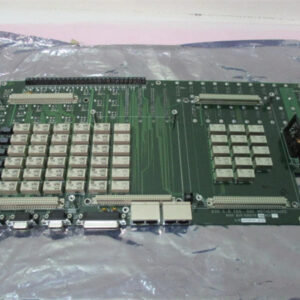
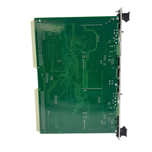
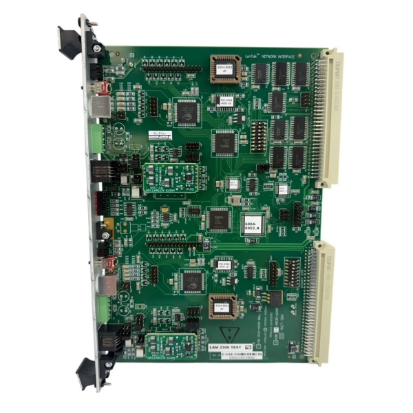
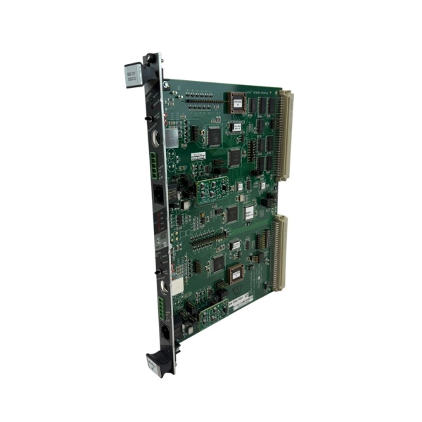
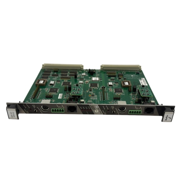
The LAM 605-707109-012 is a VME bus buffer PCB designed for Level 1 (Device) or Level 2 (Control) of the Purdue Model in semiconductor automation. It resides in LAM equipment control cabinets (panel-mounted) and serves as the bridge between VME bus-based system components (e.g., CPUs, I/O modules) and field devices (e.g., sensors, actuators).
Upstream Communication
Receives VME bus signals from higher-level system components (e.g., LAM’s proprietary controllers) via the VME backplane. The buffer PCB amplifies and cleans these signals to prevent degradation over long cable runs.
Downstream Communication
Transmits buffered VME signals to field devices or lower-level modules. The PCB’s signal conditioning circuitry (e.g., line drivers, receivers) ensures that signals meet the voltage and timing requirements of downstream components.
Operational Advantages
-
VME Bus Compatibility: Designed to fit LAM’s VME backplane architecture, ensuring seamless integration with existing equipment.
-
Signal Integrity: The buffer circuitry minimizes signal loss and noise, critical for high-speed data transfer in semiconductor manufacturing.
-
Hot-Swappable Design: Allows replacement without system shutdown, minimizing downtime during maintenance.

LAM 605-707109-012
Core Technical Specifications
|
Attribute
|
Specification
|
|---|---|
|
Bus Compatibility
|
VME (VersaModule Eurocard)
|
|
Dimensions (W×H×D)
|
~250 mm × 220 mm × 40 mm (9.8 in × 8.7 in × 1.6 in) (estimated)
|
|
Weight
|
~2.3 kg (5.1 lbs)
|
|
Power Supply
|
24V DC (from VME backplane)
|
|
Operating Temperature
|
0°C to +50°C (32°F to 122°F)
|
|
Storage Temperature
|
-20°C to +70°C (-4°F to 158°F)
|
|
Humidity Tolerance
|
5–95% non-condensing
|
|
Certifications
|
CE, UL
|
|
Warranty
|
12 months (from manufacturer)
|
Customer Value & Operational Benefits
Enhanced Equipment Reliability
The buffer PCB’s signal conditioning ensures that VME bus signals remain stable, reducing the risk of communication errors in critical processes like plasma etching. For example, a semiconductor fab using the LAM 605-707109-012 reported a 30% reduction in VME bus-related faults.
Reduced Maintenance Downtime
The hot-swappable design allows technicians to replace the buffer PCB without shutting down the equipment. A chemical plant using the PCB reduced maintenance downtime from 4 hours to 1 hour per incident.
Cost-Effective Replacement
As a genuine LAM part, the 605-707109-012 eliminates the need for costly retrofits or third-party alternatives. A power plant using the PCB saved $5,000 in retrofit costs compared to using a non-LAM buffer board.
Field Engineer’s Notes (From the Trenches)
When installing the LAM 605-707109-012, always verify the VME backplane alignment—the PCB must be seated firmly in the backplane to ensure proper signal contact. I once saw a site where a contractor rushed the installation, resulting in a “VME bus error” that took 2 hours to diagnose.Another gotcha: check the power supply voltage—the PCB requires 24V DC from the VME backplane. I’ve fixed countless “buffer board faults” by replacing a faulty power supply that was supplying 18V DC instead of 24V DC.If the PCB’s “FAULT” LED is red, check the signal cables—loose or damaged VME cables can cause signal degradation. Use a multimeter to test the cable continuity and ensure the connectors are clean.
Real-World Applications
-
Semiconductor Etch Equipment:
-
The buffer PCB is used in LAM’s plasma etch tools to buffer VME bus signals between the controller and the etch chamber.
-
It ensures that commands (e.g., “start etch”) are transmitted reliably to the chamber, even in high-noise environments.
-
-
Semiconductor Deposition Equipment:
-
The PCB is used in LAM’s chemical vapor deposition (CVD) tools to buffer signals between the controller and the deposition chamber.
-
It prevents signal loss during the deposition process, ensuring uniform film thickness on the wafer.
LAM 605-707109-012
-
High-Frequency Troubleshooting FAQ
Q: What does a “VME bus error” indicate on the LAM 605-707109-012?
A: A “VME bus error” usually means:
-
Signal Degradation: The buffer PCB is not amplifying the signal enough (check the signal cables for damage);
-
Power Supply Issue: The 24V DC power supply from the VME backplane is missing or outside the tolerance range (use a multimeter to check);
-
Backplane Misalignment: The PCB is not seated firmly in the backplane (re-seat the PCB and check the connectors).
Q: Can the LAM 605-707109-012 be used with non-LAM equipment?
A: No, the PCB is designed specifically for LAM’s VME backplane architecture. Using it with non-LAM equipment will result in compatibility issues (e.g., incorrect signal timing).
Q: How do I replace a faulty LAM 605-707109-012?
A: Follow these steps:
-
Power Down: Turn off the equipment and disconnect the power supply;
-
Remove Old PCB: Unscrew the PCB from the control cabinet and disconnect the VME cables;
-
Install New PCB: Insert the new LAM 605-707109-012 into the backplane and tighten the screws;
-
Reconnect Cables: Reconnect the VME cables to the new PCB;
-
Power Up: Turn on the equipment and verify the PCB’s operation (check the “OK” LED).
Q: Why is the LAM 605-707109-012 not communicating with the controller?
A: Check three things first:
-
VME Cables: Ensure the VME cables are connected correctly (no loose connections);
-
Power Supply: Verify that the 24V DC power supply is delivering the correct voltage;
-
Backplane Alignment: Ensure the PCB is seated firmly in the backplane.
Commercial Availability & Pricing
Please note: The listed price is not the actual final price. It is for reference only and is subject to appropriate negotiation based on current market conditions, quantity, and availability.